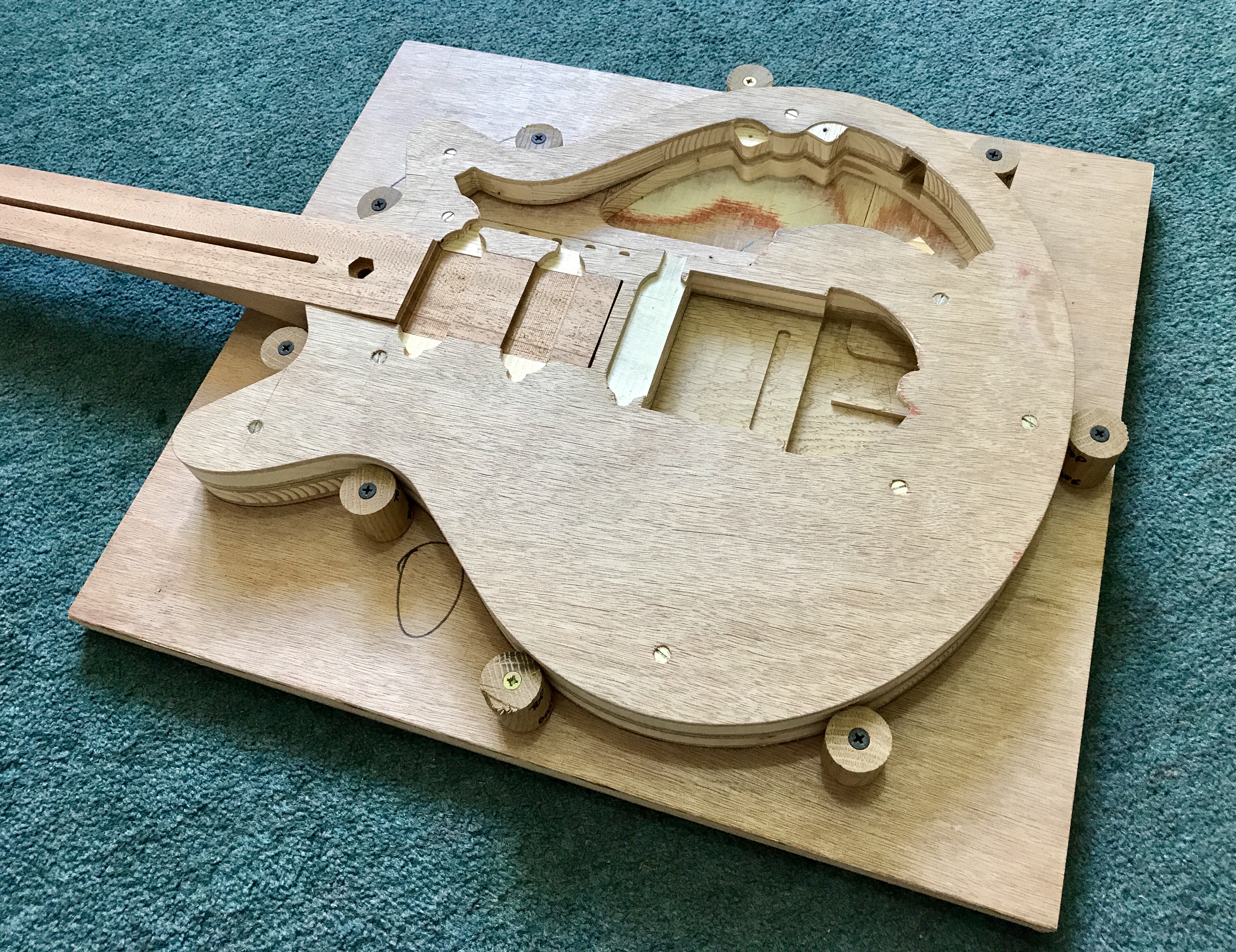
After cutting the body sections I began assembling the body for my Brian May Red Special replica guitar. To facilitate this I made a body section alignment jig by re-purposing a piece of slightly warped blockboard to form the base and lengths of oak dowel to make support pillars for the control plate.
I cut 1″ diameter oak dowel into several 30 mm high sections using my Makita 2704 table saw, pilot drilled them, drilled a countersink in the top to make the screw head flush, secured the lower body section in place with double sided adhesive tape, screwed the dowel sections in place and laid up the upper section before screwing it in place (no glue for the test body yet). The images in the gallery below illustrate the test body and rough cut Khaya neck inserted into the alignment jig. This was required to open out the neck mortise.


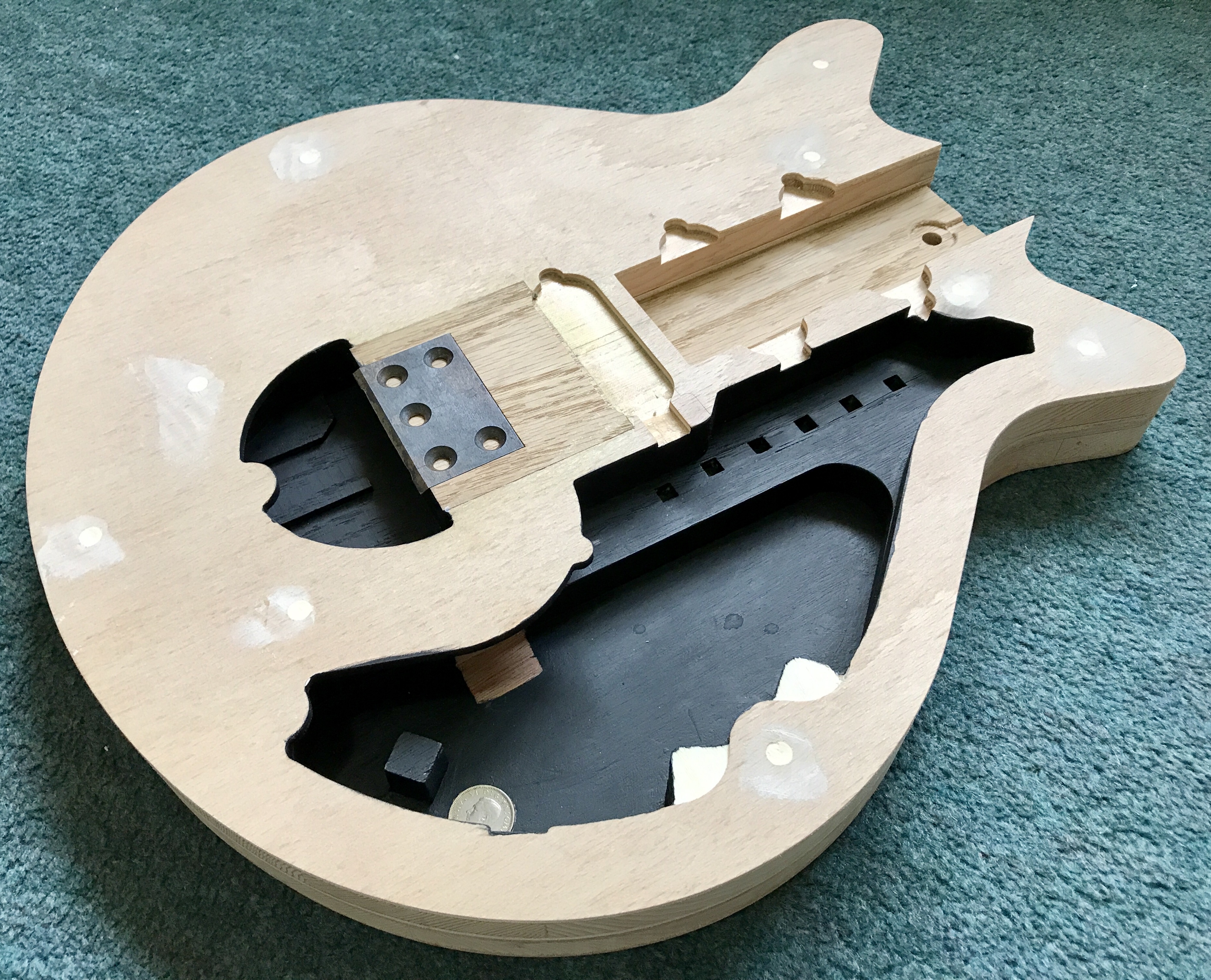
When the body section alignment jig was ready, I inserted the final body upper section and screwed through the upper section of the test body to mark out the positions of the holes for the body fixing screws. I then fitted the final body upper and lower sections and drilled and countersunk pilot holes for the body fixing screws. Then I painted the exposed cavities with Rustins Blackboard Paint, glued the body sections together and glued in the small oak insert with tremolo bolt retaining bar with wood glue. I filled in the remaining screw head countersink with wood filler and abraded it flush with the wood.
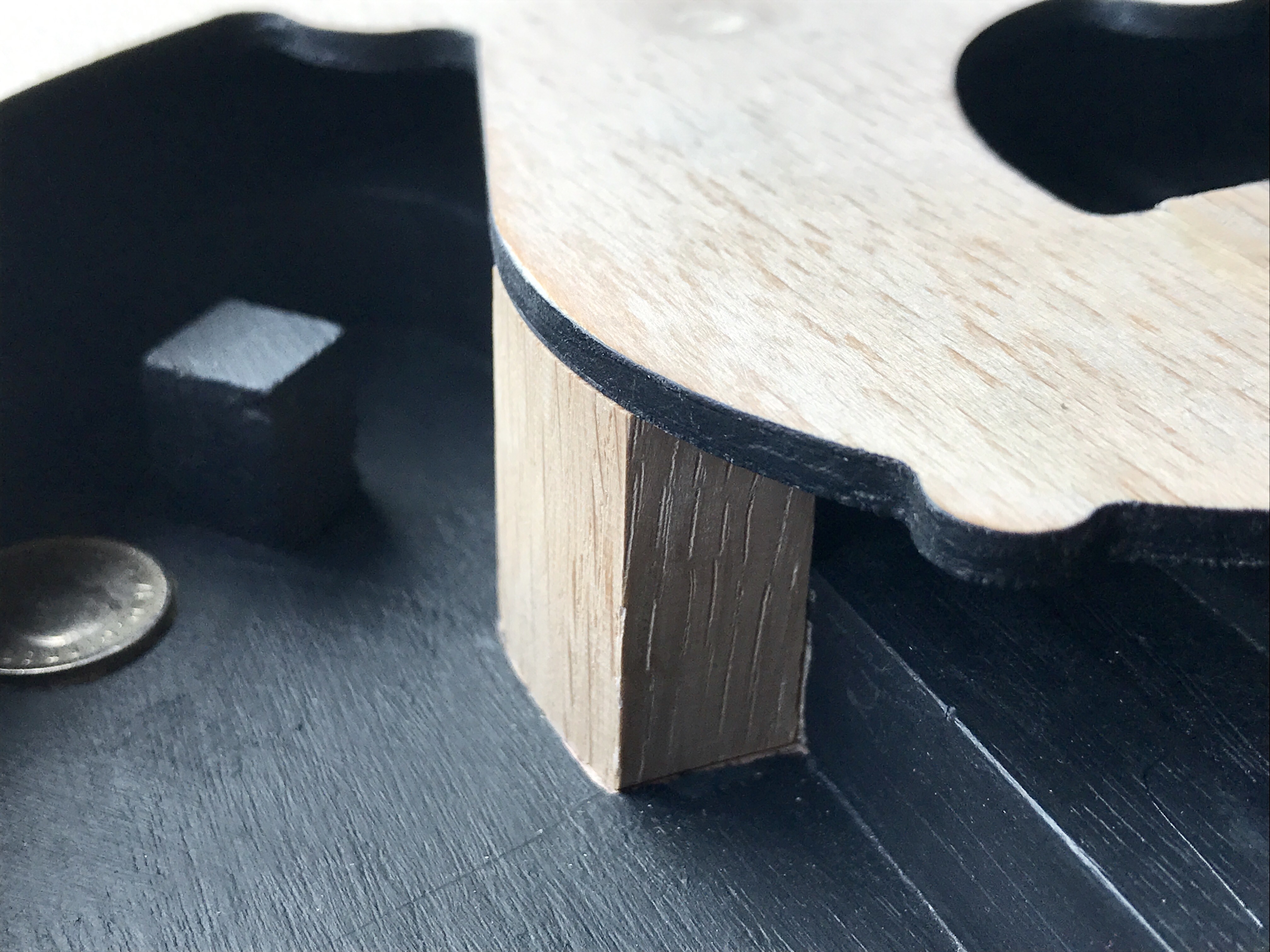
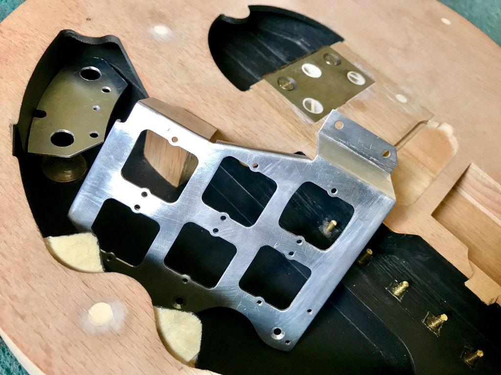
I also glued in a sixpence where the tone potentiometer body will be situated as fitted to Brian May’s original Red Special guitar. I presume that this was added by Brian to take up the space between the bottom of the tone potentiometer and the floor of the control cavity to ensure a good earth/ground connection with the control cavity shielding foil. I used a sixpence from the same year Brian was born (1947). The images in the next gallery illustrate the assembled body after this work was complete with the tremolo knife edge plate in place but not attached. I used my CNC machine to cut a control cavity overhang support pillar from oak; this cut very accurately, only requiring a fraction of a millimetre removed from the upper surface by abrading and illustrates how much time and effort CNC can save over making these parts manually.
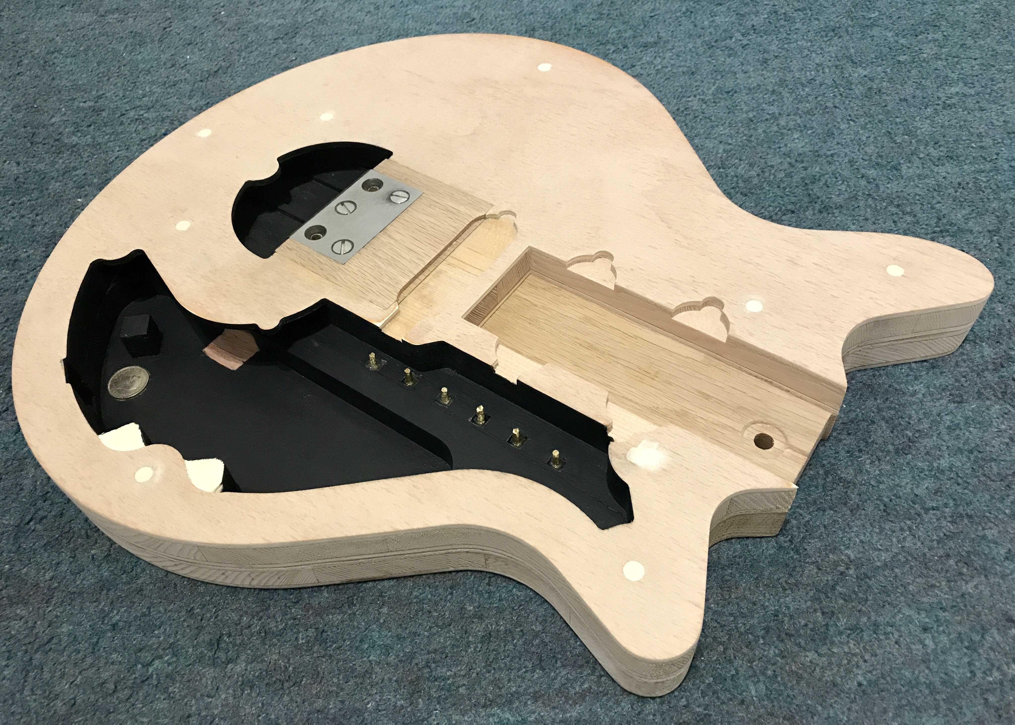
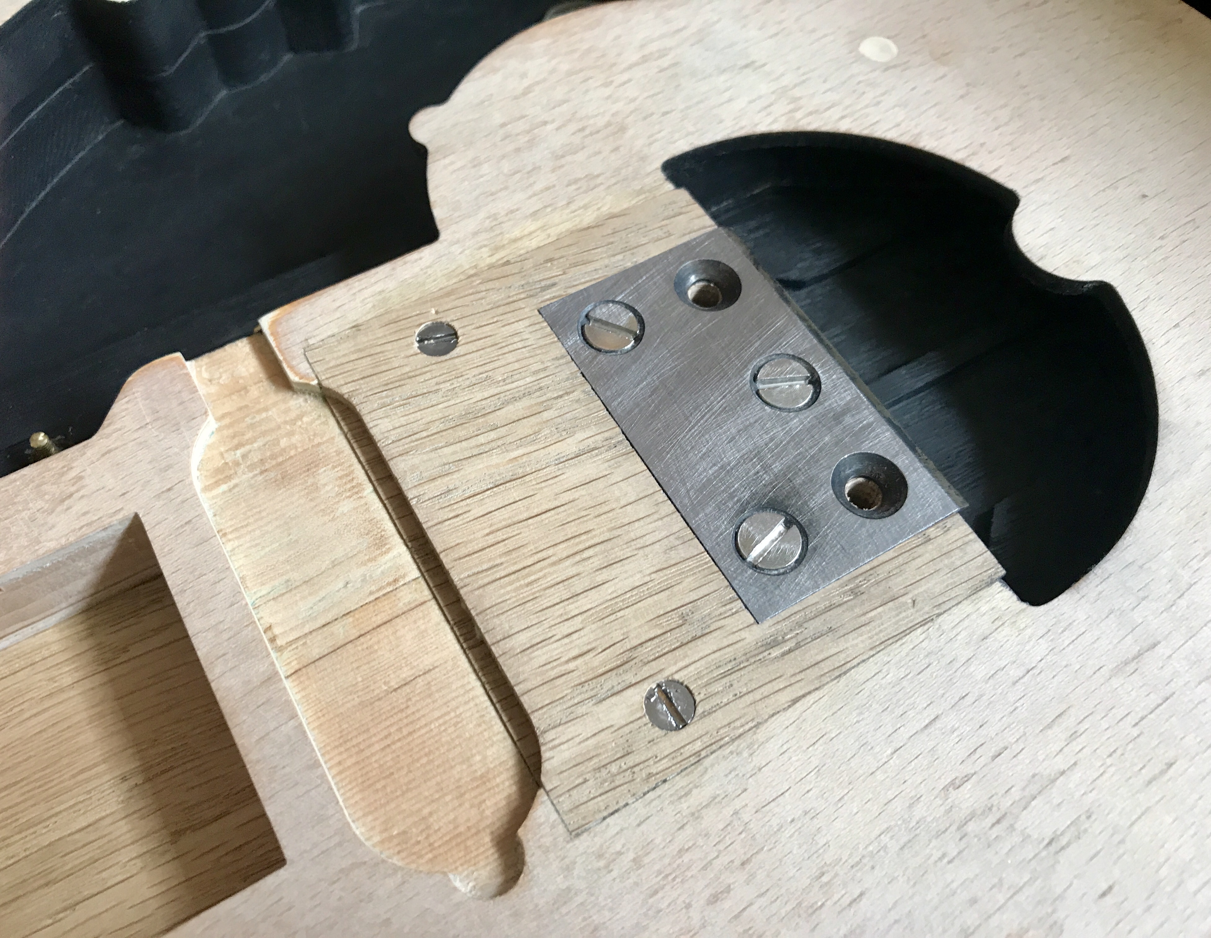
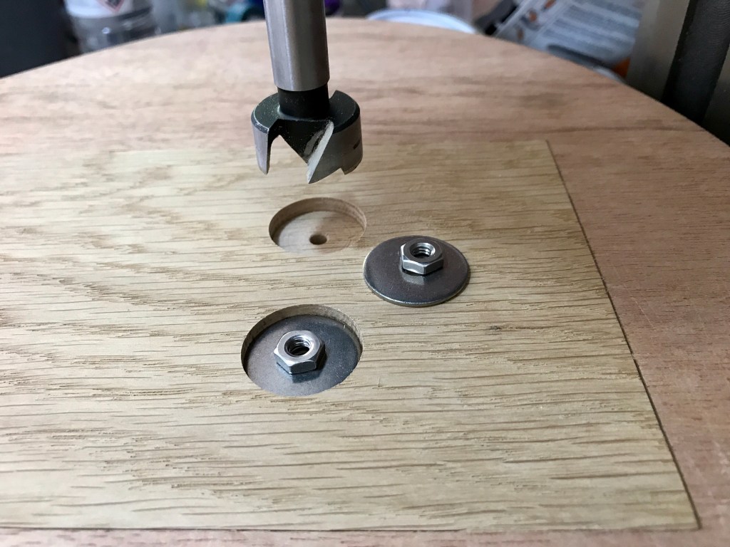
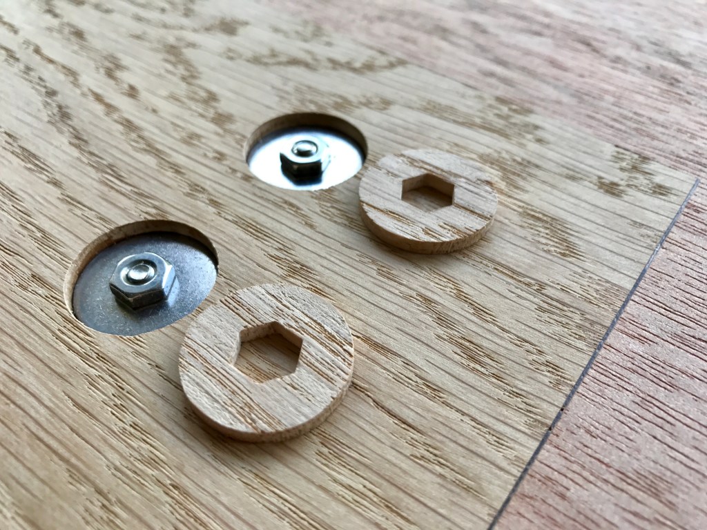
Moving on in the body assembly process, I glued and screwed in the knife edge plate, added additional securing screws in the small oak block in the upper section which I almost overlooked, set in sections of 6BA brass machine screws into the cuboid rebates with epoxy resin to act as polarity posts and added stainless steel penny washers rebated into the rear of the large oak insert in the lower body section. I drilled 3/16″ holes through the body and 4.7 mm deep circular rebates into the back of the oak insert on the lower body section using a 25 mm Bosch Forstner drill bit, glued in the 1″ diameter, nominally 1/16″ (1.5 mm) thick stainless steel repair washers, inserted the stainless steel machine screws and 3/16″ thread hex nuts then secured these with a Loctite threadlock adhesive.
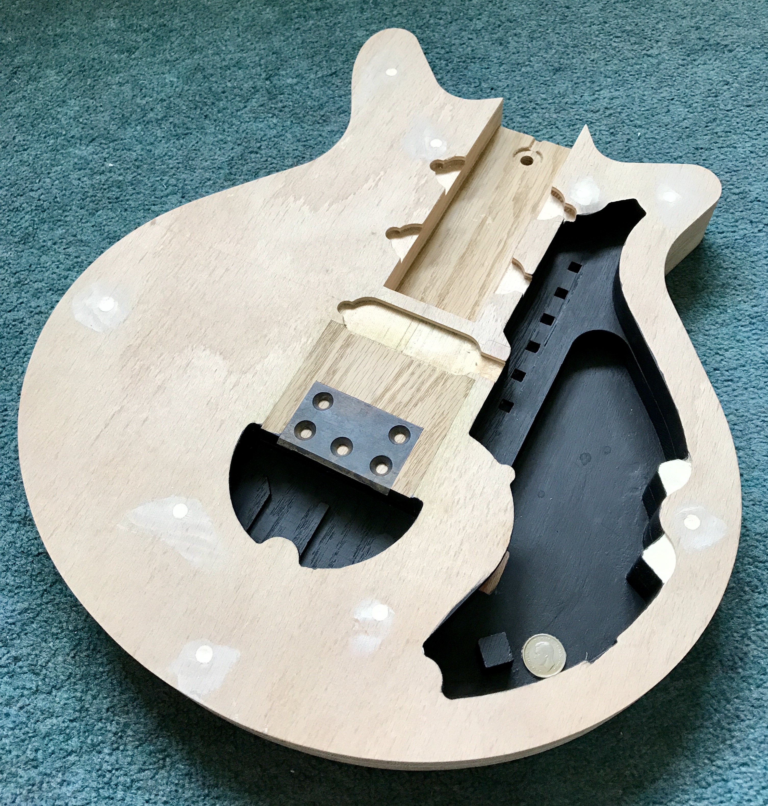
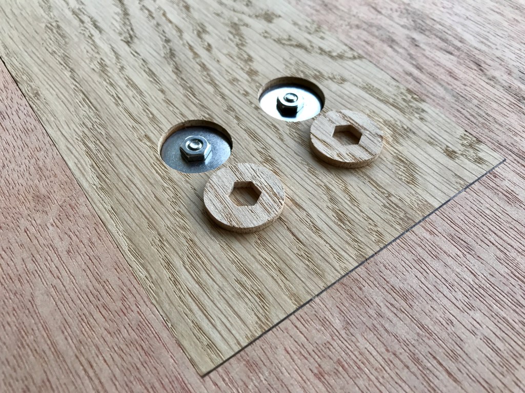
I used my CNC machine again to reduce the thickness of an oak panel to 1/8″ using a large diameter cutter. Then using a 2 mm diameter 2 flute bit, cut the oak plugs with hexagonal hole and filed the corners out a little with a diamond file. The oak plugs were glued in using superglue and abraded flush with the surface. I filled over the countersunk machine screw heads with epoxy resin and the wood screw heads with Ronseal wood filler, allowed these to dry then abraded flush with the surfaces.
Next article:
Parts 34-36: Veneering the Body
Previous article:
Parts 29 and 30: Veneering and Staining Tests
