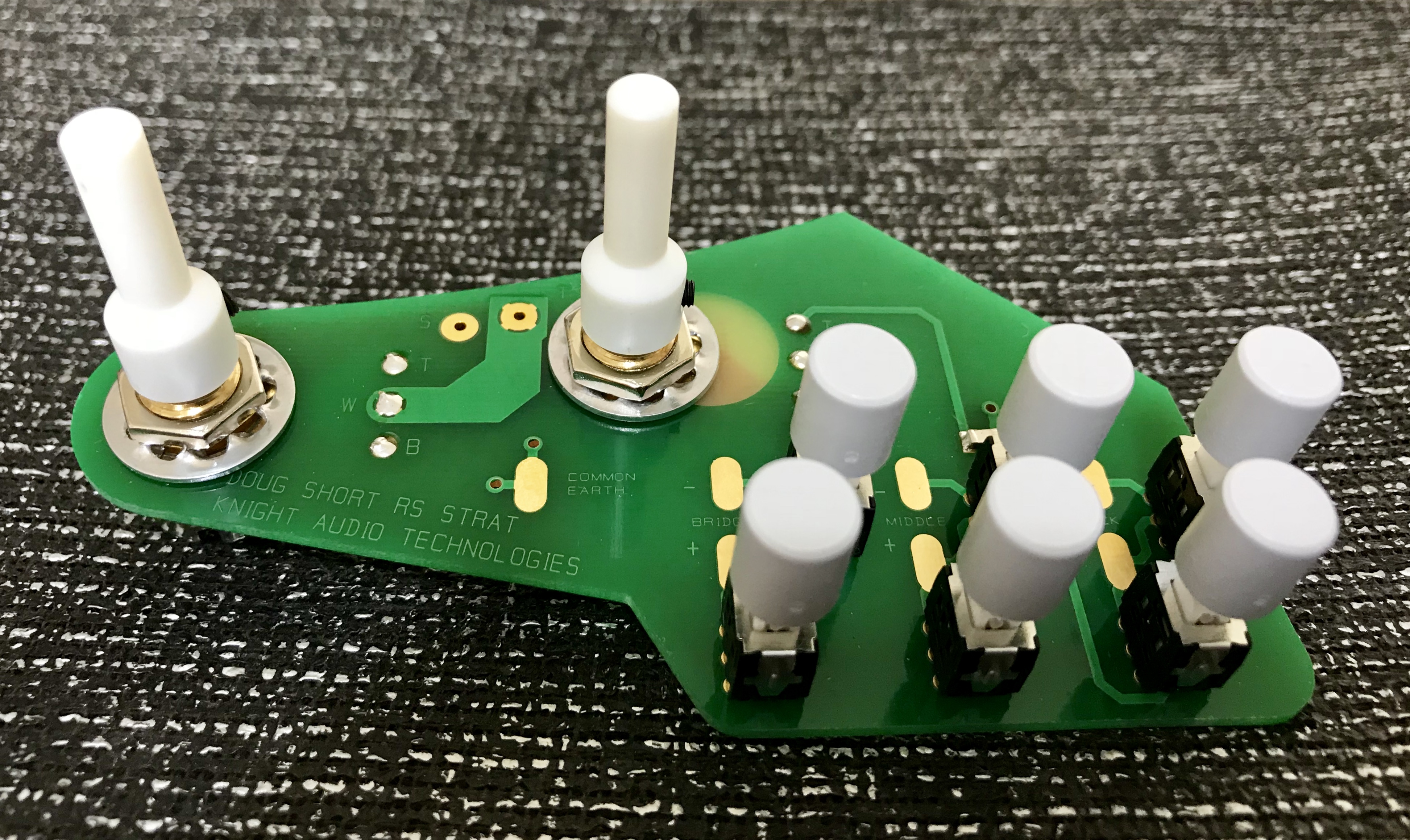
Once I had received the custom printed circuit board (PCB) designed by Nigel Knight of Knight Audio Technologies which was based on the Guyton RS Transporter but without the on-board treble booster, I progressed what became plan B. I had to determine the best positions to drill the mounting holes, drill them and then design a carrier plate which would be CNC cut from nominally 4 mm thick perspex, have brass threaded inserts thermoset into the plastic and glued to the underside of the pickguard. I am grateful to Nigel Knight of Knight Audio Technologies for suggesting this mounting solution.
After careful consideration due to the relatively high cost of the one-off custom PCB, I decided to drill three 1/8″ (3.2 mm) diameter mounting holes between the neck pickup on/off and phase reversal switches, at the far left edge and to the right of the tone potentiometer looking down on the module. This would support the switches and tone potentiometer region leaving the volume potentiometer to be supported by inserting a pad underneath it to take up the 1/4″ gap to the bottom of the control cavity.
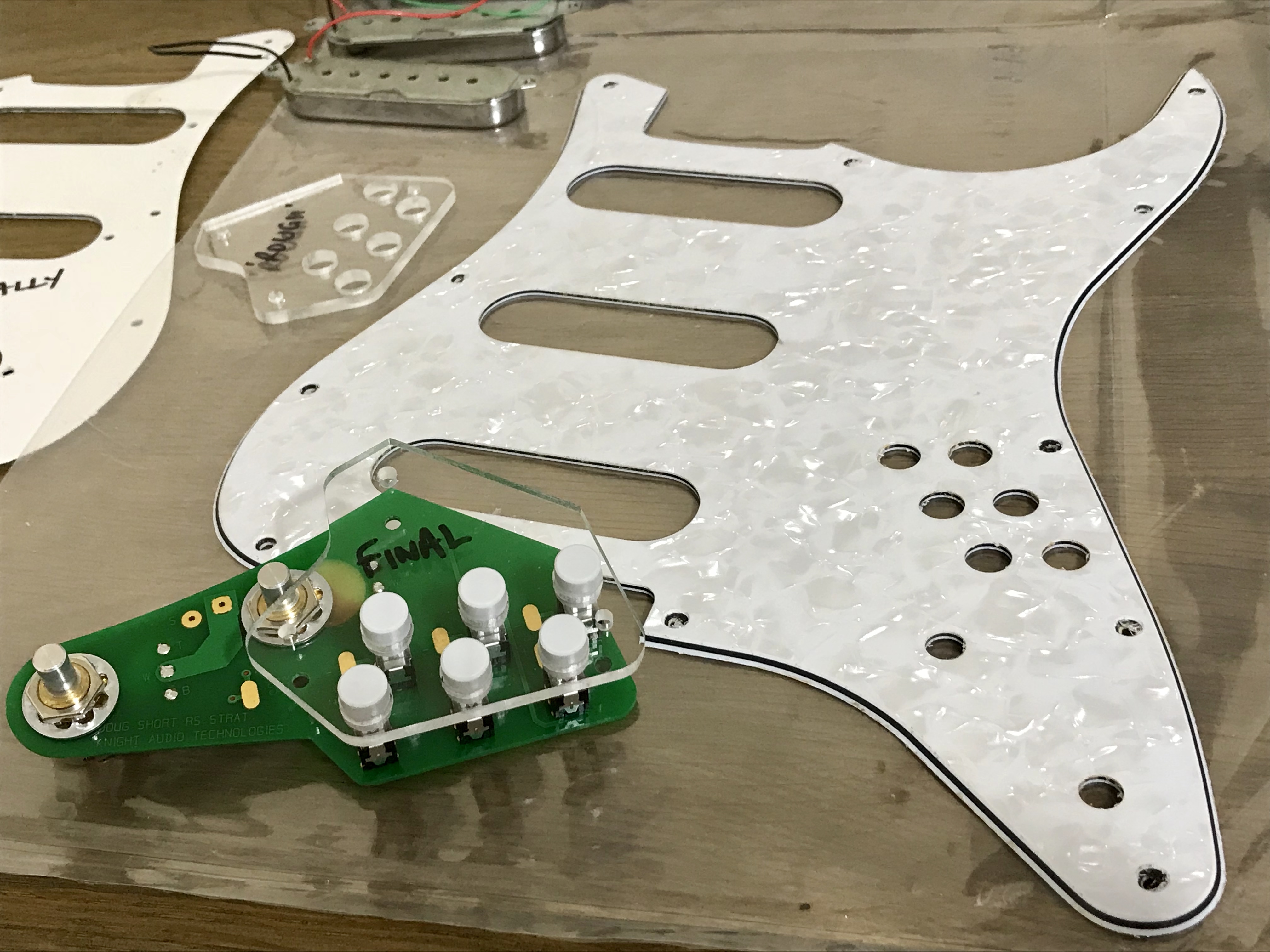
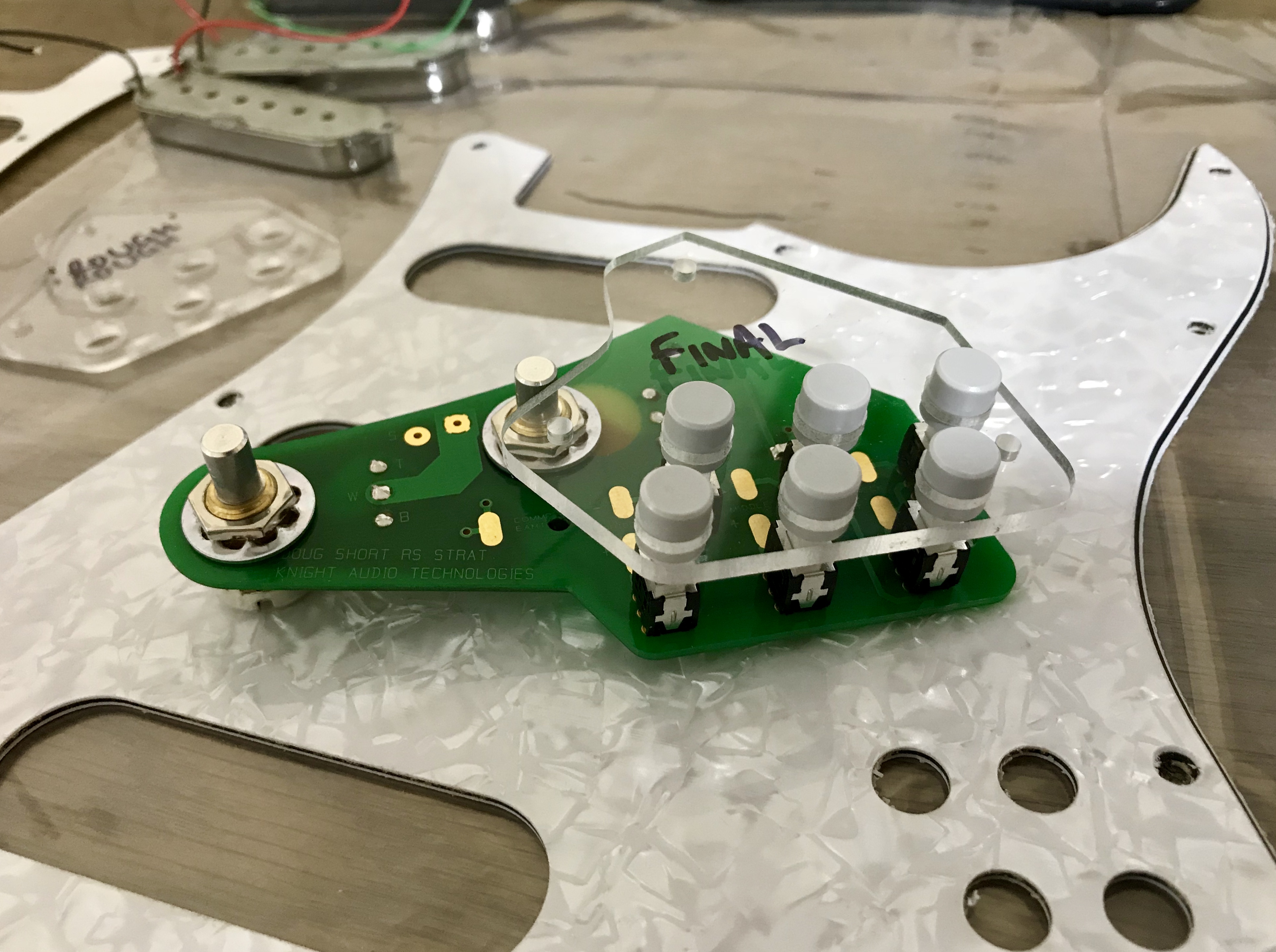
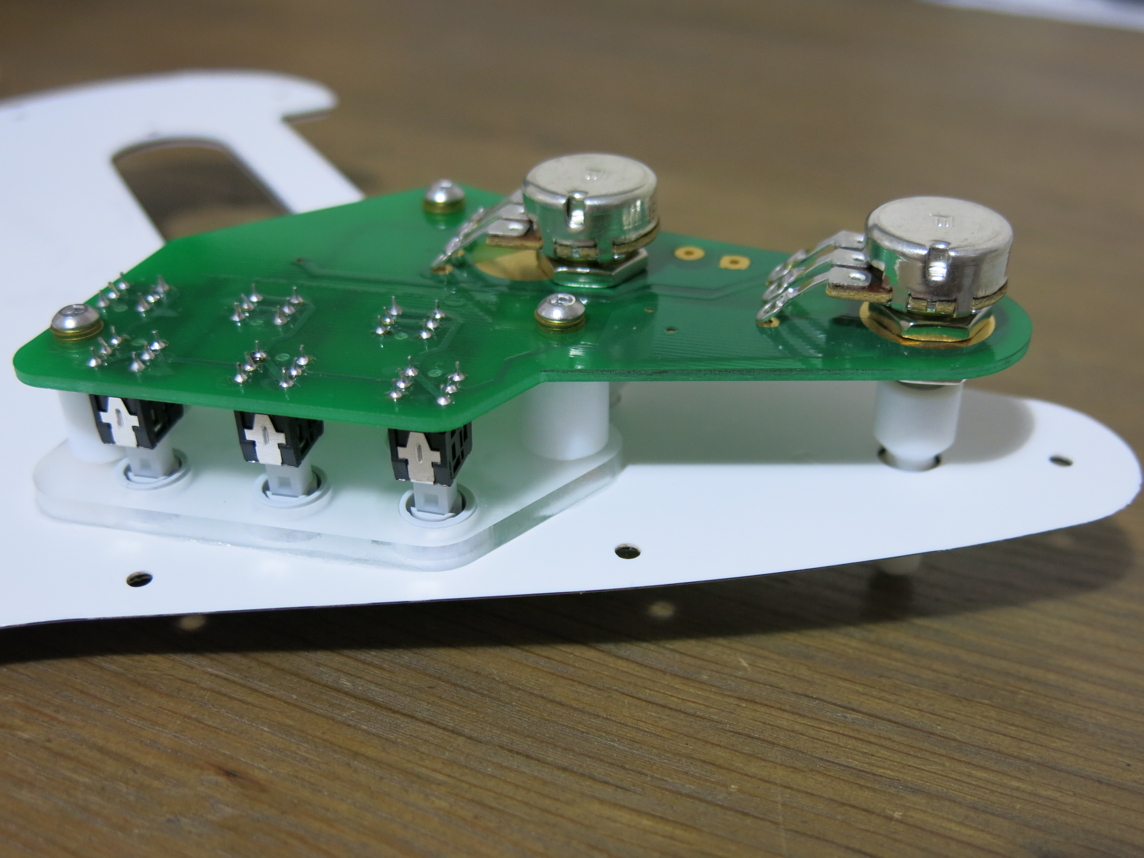
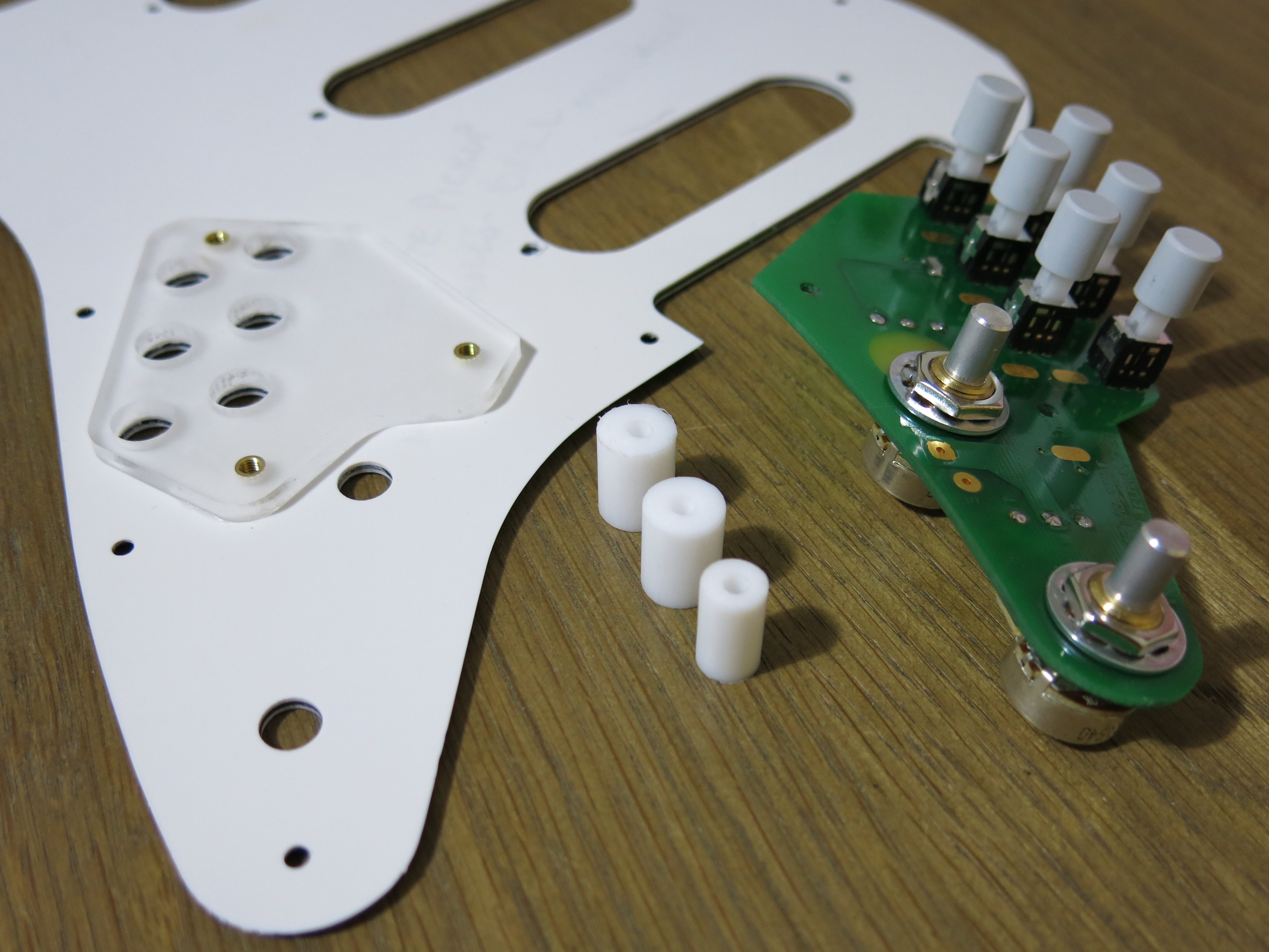
The pictures in the gallery below illustrate the final pickguard cut from 2.5 mm thick 3 ply (white/black/white) pearloid finish PVC and two of the perspex carrier plates. I made several and chose the two which had the most accurately drilled mounting holes as test piece for the white pickguard and a final piece for the pearloid pickguard. I deleted the pickup mounting holes from the final CNC cut toolpath because they are not precisely placed on the hand made pickups and so it is easier to insert the pickups, mark the actual hole positions then drill them manually.
The short embedded video below illustrates the stages involved with thermosetting M3 brass threaded inserts into the perspex plastic. The initial holes were drilled to 1/8″ (3.2 mm) diameter. After holding the carrier plate down on my drill press bed with double sided adhesive tape, I first locate the hole using the 1/8″ drill bit, then I swap to a 3.5 mm drill bit and open out the hole. Then I insert a length of M3 stainless steel machine screw with the brass threaded insert on the end. I heat this using an electric heat gun and slowly press it into the 3.5 mm hole.
Once all three inserts were thermoset into the plastic, I filed off the excess with a diamond file and dressed the plastic surfaces with 320 grit abrasive paper prior to gluing onto the underside of the pickguard. To complete the mounting solution, I made three stand-offs from PTFE rod centre-drilled to 1/8″ (3.2 mm) diameter. Two of the rods were around 10.5 mm diameter and one around 8.7 mm diameter. The smaller diameter stand-off is for the region between the neck pickup on/off and phase reversal switches.
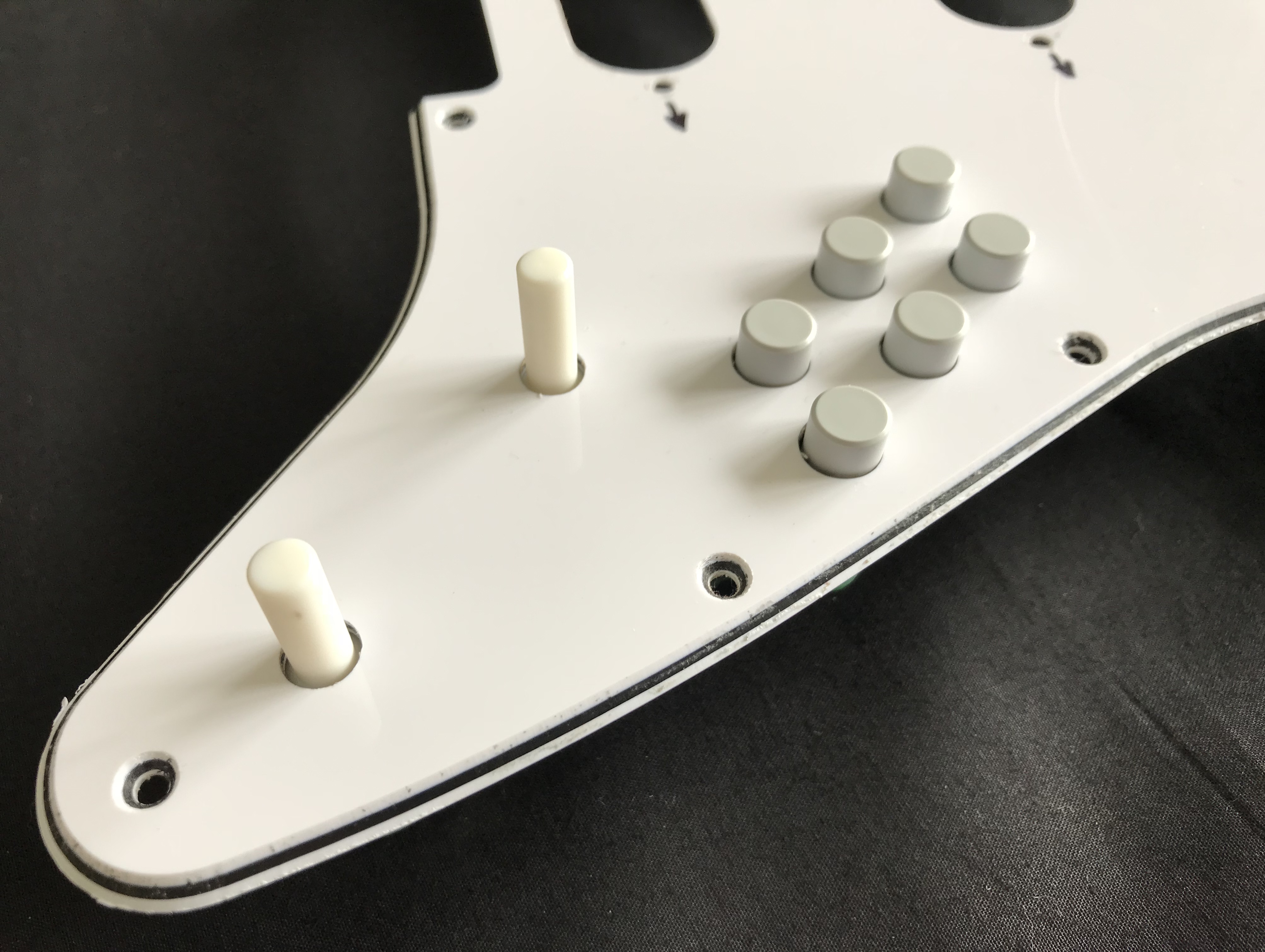
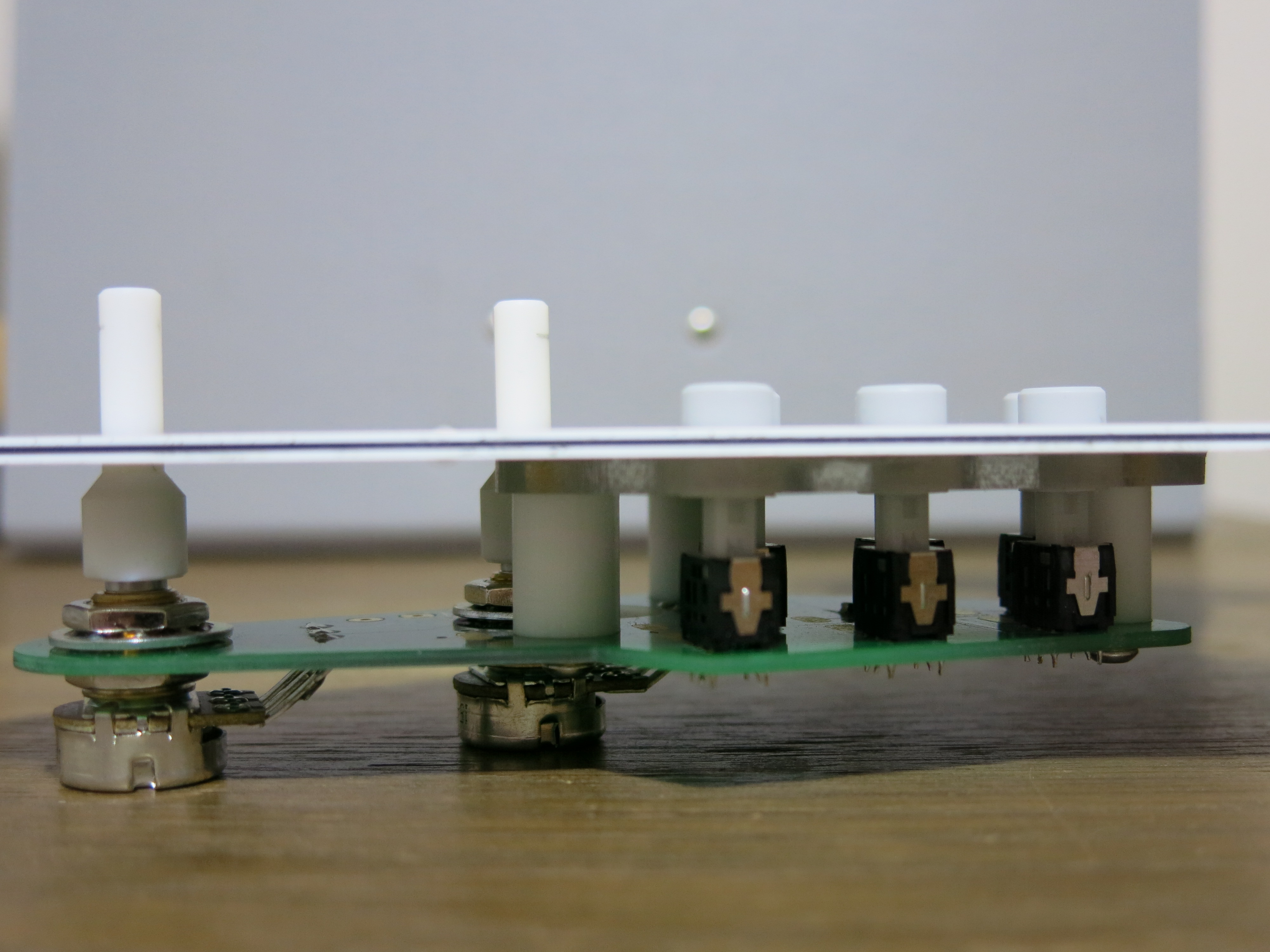
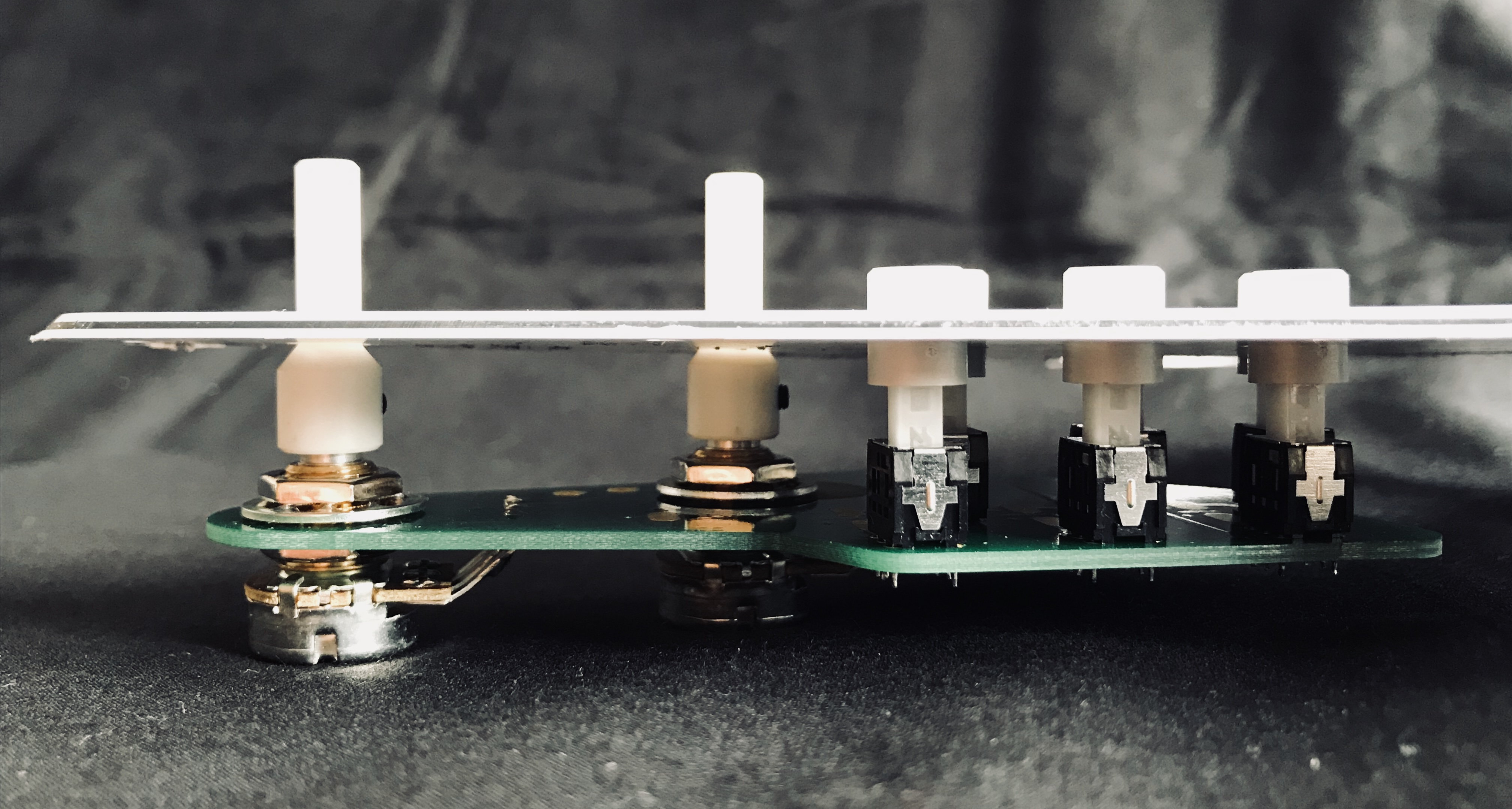
Test fitting showed that mounting the PCB 18 mm below the pickguard resulted in the unactuated switch caps being 4 mm above the pickguard which looked good to my eye. I then measured the thickness of the perspex plate accurately with digital calipers and milled the PTFE stand-offs to the required height; the perspex was nominally 4.0 mm thick but the actual thickness varied from 3.55 to 3.75 mm thick requiring two stand-offs to be 14.45 mm high and one to be 14.25 mm high.


Mounting the PCB to the carrier plate with M3 stainless steel machine screws in the 1/8″ (3.2 mm) holes allowed for a small degree of adjustment to precisely locate the switch caps in the holes. I glued the carrier plate to the underside of the pickguard using cyanoacrylate superglue. I used two small sections of nylon rod milled to the correct diameter to locate the holes in the correct positions.
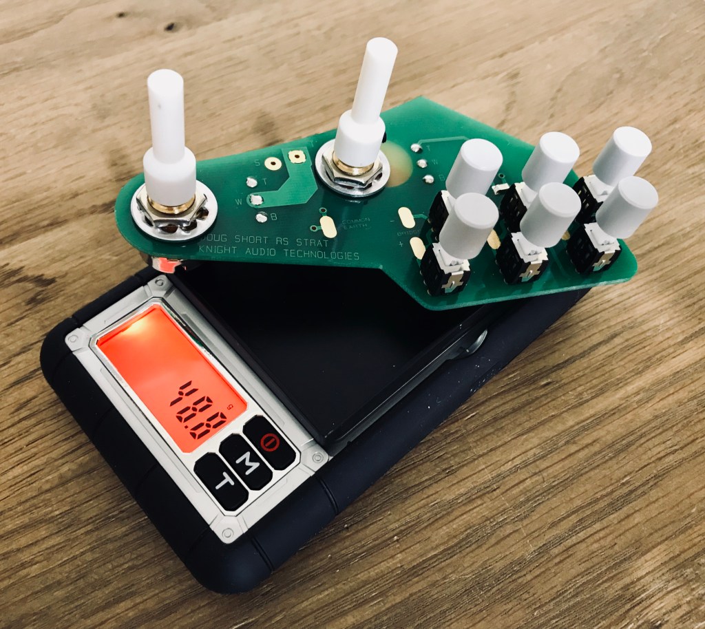
I decided to mount a set of plastic potentiometer shaft extenders to save mass compared to the stainless steel versions provided by Nigel which approximately doubled the mass of the PCB itself from 40 to 80 grams. The KAT items weigh approximately 40 grams compared to the nylon pieces which weigh only 2-3 grams. I felt, on reflection, that any weight saving is worth having to avoid stress on the PCB. These also required to be milled down to remove 4 mm from the length to allow the Anotone aluminium control knobs to fit over them.
Next article:
Part 9: Final Assembly and Testing
Previous article:
Part 7: Mechanical Set-up
