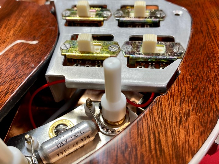
I completed wiring up my Brian May Red Special replica guitar’s electronics on 6th June 2020 and thankfully, all was well on the first test through a straightforward signal chain consisting of a Rangemaster style treble booster and Vox AC30 TBX. The tone was bright and clear with no crackling or extraneous noise. The rest of post is a summary of some of the pertinent aspects of the wiring scheme. Nigel Knight of Knight Audio Technologies (KAT) features prominently in this discussion, for two reasons. Firstly, he wired up the switch frame and potentiometer/capacitor plate for me in a facsimile of the original guitar using a mix of vintage NOS components (Jeanrenaud DPDT parallel slide switches), modern items (Bourns potentiometers) and pastiche replicas (modern Vishay polyester capacitor hidden inside the bare casing of a vintage item). Secondly, I followed or acknowledged most of the pragmatic tips he set out in the write-up for his first KAT Burns Special conversion project in September 2014. He generously made his documents available on the Red Special web forum as PDF files. If you are not a member you can download his summary and wiring diagram pictured below here:

Because I tried to design the internal detail of the guitar to be as close to the original (as documented by Greg Fryer prior to his 1998 restoration) as I could discern, I had to modify Bulgin 1/4″ jack socket to fit the rebate. These changes including making a custom sized rectangular Tufnol butt plate, snipping off the front terminal lug, twisting the rear terminal lug inwards through 90 degrees and filing it away near the jack base to avoid it fouling the cavity wall. I also affixed a strip of black insulation tape to the cavity wall to guard against inadvertent grounding.
If you are reading this as background research before attempting the job yourself, I recommend planning the installation so that it breaks down into sub-assemblies. I don’t cover wiring of the switch frame and pot/cap plate sub-assembly here because Nigel did this and I illustrated the process in several earlier posts, including on my 3/4 scale “1975” Brian May Red Special where I used jumper wires. Two key tips from Nigel’s professional experience are to minimise all wire lengths inside the guitar to avoid them acting as aerials to pick up radiofrequency (RF) interference and to strain-relieve all connections. This is perhaps less important when playing occasionally at home but becomes a vital consideration if you are a professional or semi-professional musician to avoid embarrassing and potentially career-limiting technical failures in front of paying customers.
I soldered a length of black hookup wire to the top (barrel) terminal lug on the Bulgin 1/4″ jack socket. Nigel Knight recommends that this is kept as short as possible and is grounded to the control cavity wall shielding as close as possible to the jack socket to dump RF signal to ground at the entry point of the signal. I inserted the jack socket and secured it in place using the external hex nut and a thin fibre washer.

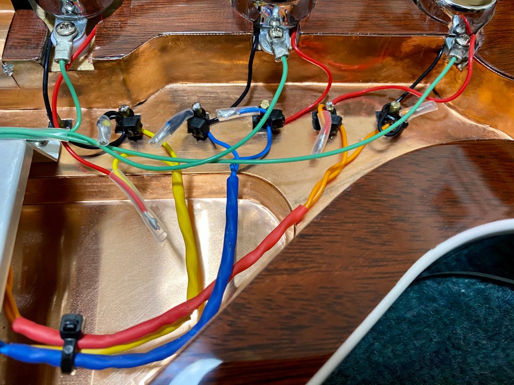
I installed the pickups as described previously and trimmed excess length from the red, black and green earth hookup wires. I initially trimmed the red and black hookup wires trimmed to approximately 3″ long. I elected to terminate the three green pickup casing earth wires in a single crimp ring terminal lug screwed to the foot of the switch frame, although Nigel recommends keeping these as short as possible and soldering them individually to the copper cavity shielding on the ledge. I trimmed the green pickup casing wires to final lengths of 2″, 4″ and 6″ for bridge, middle and neck respectively, stripped the ends and pre-tinned them.
I have never been a particularly skilful solderer so I asked Nigel for some tips. The first was to use multicore 0.7 mm lead solder which has a relatively low melting point of 183°C (RS Components stock no. 555-235). The second was to get a decent soldering station. Most professionals prefer Weller brand so I upgraded to a used Weller WD1 from eBay in March 2018. The difference to my Maplin budget version is noticeable.
After trimming the wires to their final lengths, I turned to the pickup and switch connections. The “original BM/Guyton” specification Adeson Burns Tri-Sonic pickups have the middle pickup made with the bar magnet poles reversed so that when it is connected in reverse wired, reverse magnet polarity (“RWRP”) configuration it will act as a humbucking pair with the normal polarity bridge pickup. In this arrangement, Brian’s favoured pickup combination of bridge and middle in phase will humbuck. I confirmed this using a needle compass because I had discarded the printed circuit diagram that Adrian Turner included with the pickups. You can see the result in the attached video clip. As an aside, there has been a lot of debate amongst knowledgeable enthusiasts about whether the RWRP pickup on the Red Special has changed over the years from the bridge to the middle position. Indeed, if I recall correctly, the prototype set of Adeson pickups fitted to my Stratocaster has the bridge pickup RWRP.
In attempting to follow Nigel’s recommendation of deploying strain relief at the six terminal posts (which I suspect were installed by Brian and Harold so that they could test different wiring configurations), I struggled to get solder to adhere to the tops, probably because they had some residual epoxy resin in situ. The only suitable means of providing strain relief I had to hand were small black cable ties. This being the case, I elected to use the terminal posts only as anchors for the cable tie and simply soldered the tinned ends of the pickup wires and switch wires together then covered them with a short section of silicone sleeving. I bundled each twisted pair together with coloured polyolefin heat shrink sleeving and a single cable tie. It was necessary to establish which of the two switch wires was positive using the continuity checking function of a multimeter because each strand of the twisted pair (three to four twists per inch if you’re interested in this level of detail) is identical.


Some additional work is required before the guitar can be signed off as finished. I need to complete fitting of the pickguard, including any modifications necessary (e.g. rebating near the bridge pickup mounting screw head). I need to final hand polish the body, carry out some cosmetic repairs to the headstock to correct some lacquer sand-through and wood chip-out. I ignored my own advice to tack the bakelite nut on in case it got damaged or the string spacing proved unsatisfactory and secured in place with a quantity of superglue. Already, the high E string is slightly too close to the edge, probably exacerbated by the nut being around 0.25 mm offset towards the top E. Otherwise it is satisfactory so I will live with it a while before deciding whether to correct it by making a new nut.
Previous article:
Part 59: Initial Setup (Setting the Playing Action and Pickup Installation)
