After the guitar was stripped of all its hardware and the electronic components had been removed from the pickguard, I began the process of transferring the shape of the pickguard, the cavity routing and the screw hole positions into TurboCAD. Even with diligence and care, this is a tedious process involving a lot of iteration. I tried two methods for this and obtained satisfactory results. Taking photographs is, in my experience, the least preferable option because unless the camera is oriented precisely relative to the guitar body using some kind of mounting frame, there will be too much parallax error, even if multiple photographs are taken and then manipulated in photo editing software. If you wish to attempt a project requiring a similar technique of transferring guitar features into CAD software utility, I would discourage this approach unless you have a particular skill in photography and image manipulation.
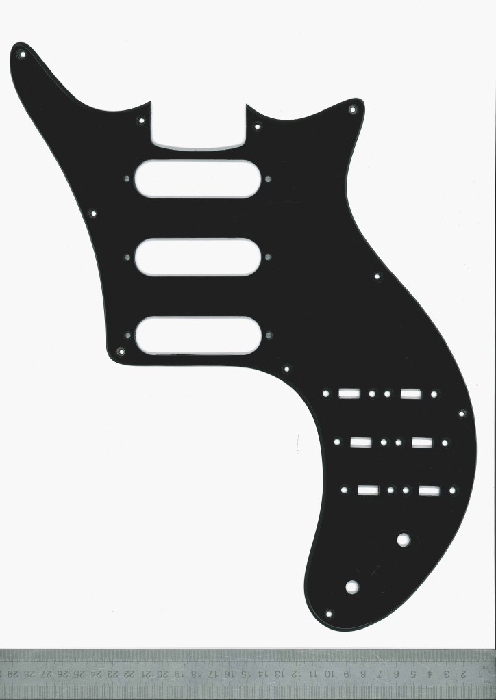
Scanning the pickguard was relatively straightforward: I used an A3 flatbed scanner set to 600 dpi and greyscale to help determine shadow from the physical object edges. A tip to assist in scaling the resulting bitmap image correctly to 1:1 size is to place an engineering ruler with fine gradations (0.5 mm) on the scanner bed next to the item that you are scanning.
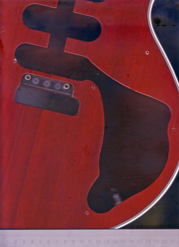
To determine the cavity routing shape and position relative to the pickguard screw holes, one of the two methods I used was to scan the guitar body. At the time of carrying out the project, I only had an A4 flatbed scanner which was challenging. At the time of writing this article, I had acquired an A3 flatbed scanner. I didn’t think this would work well enough to yield an image that was free of significant parallax error, but I felt it was worth trying in parallel with the main method I have used before. This second method involved using 100 micron thick coloured acetate film (the kind used for overhead projection transparencies in the days before digital data projectors were commonplace). I laid this over the guitar body, secured it in place with masking tape then traced over the edges with a marker pen. I then removed the film, cut out the shape with a craft knife and punched the screw holes. I then scanned the shape alongside an engineering ruler and traced over the 1:1 scaled image in TurboCAD. It might be obvious when it’s pointed out but if you use clear acetate film instead of coloured, the cutout shape will be almost invisible in the scanned image!
Once I had traced over the pickguard shape in TurboCAD using a closed bezier curve (which have learned from experience is less prone to developing glitches such as degenerative faceting during subsequent manipulation than a polyline consisting of arc and line segments), I printed it out at 1:1 scale, cut out the shape with a craft knife, overlaid it onto the guitar body and noted any adjustments that were required.
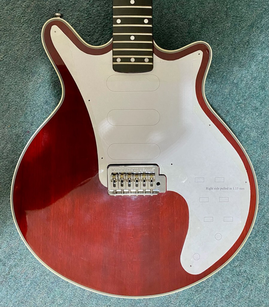
Tracing over the original pickguard and guitar body shapes is only one of the challenges in this process which, ultimately, involves a great deal of work for minimal cosmetic, functional or technical improvement to anybody who cares little about the aesthetics of the original Red Special. Once I had scanned and traced over the Burns pickguard shape and the cavity routing, I compared it critically against my interpretation of the design of the original Red Special’s pickguard to see where improvements to the shape could be made. Sometimes these tweaks were only 0.5 to 1.0 mm in magnitude.
The biggest constraint on achieving an authentic shape was the cavity width between the middle and bridge pickup switches. Achieving a close fit around the fretboard heel is reasonably challenging, although wrapping the pickguard around the tremolo plate allowed me to preserve the long curve at the left and obtain a more authentic shape in the ‘tail’ section from the bridge pickup switches to the area where the control knobs are situated.
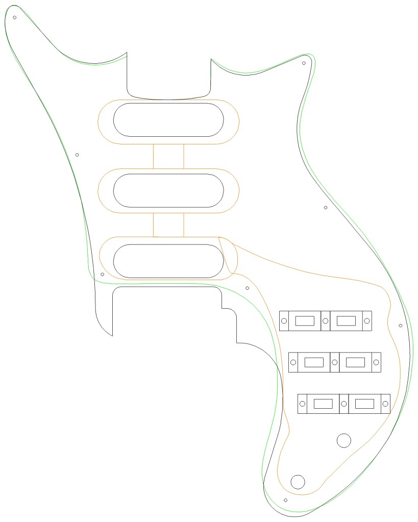
To the best of my knowledge, the pickups on Brian May’s original Red Special are spaced at 2 1/8″ (54 mm) apart. I assume that Brian originally arranged his larger home made pickups at 2″ (50.8 mm) apart but had more space to arrange the smaller Burns Tri-Sonics when he retro-fitted them hence the extra 1/8″ on each pickup. Due to the larger bridge on these commercial replicas, the pickup spacing is constrained to around 1 27/32″ or 47 mm. Because the routing dimensions are reasonably generous, I was able to increase the spacing, but only by less than 2 mm to 1 59/64″ (48.8 mm).
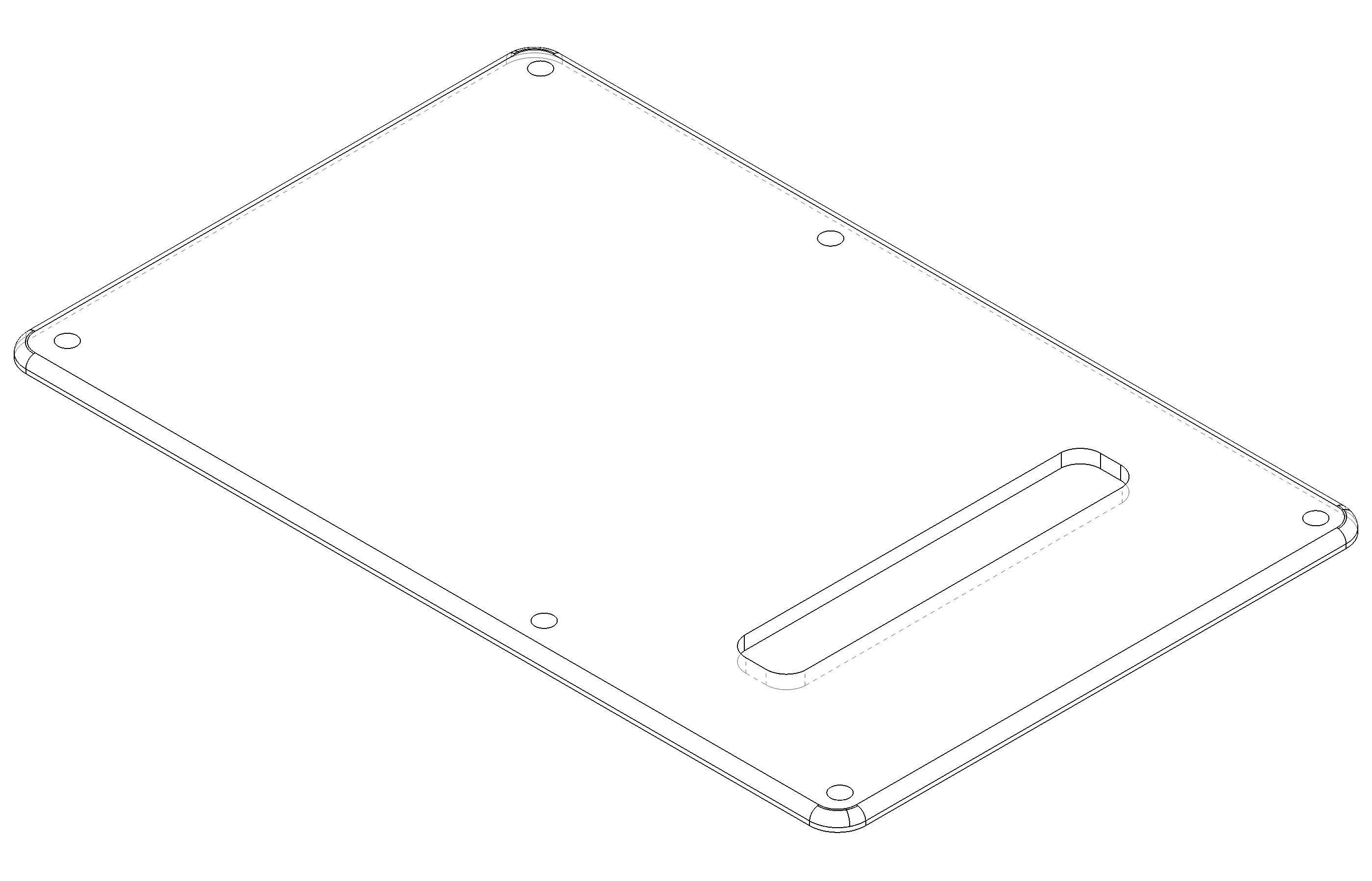
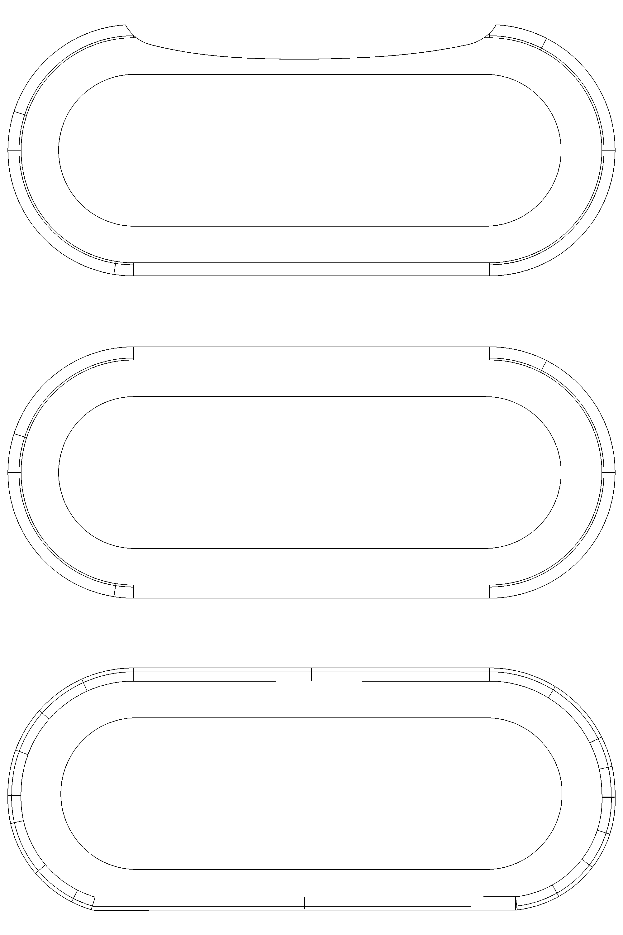
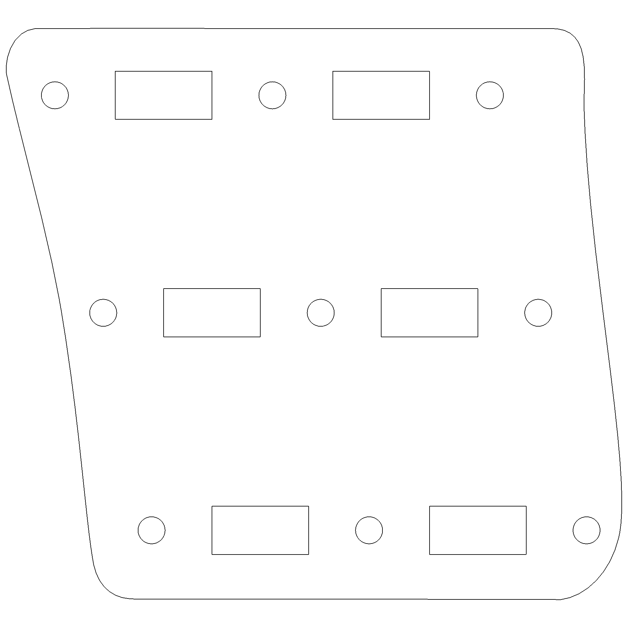
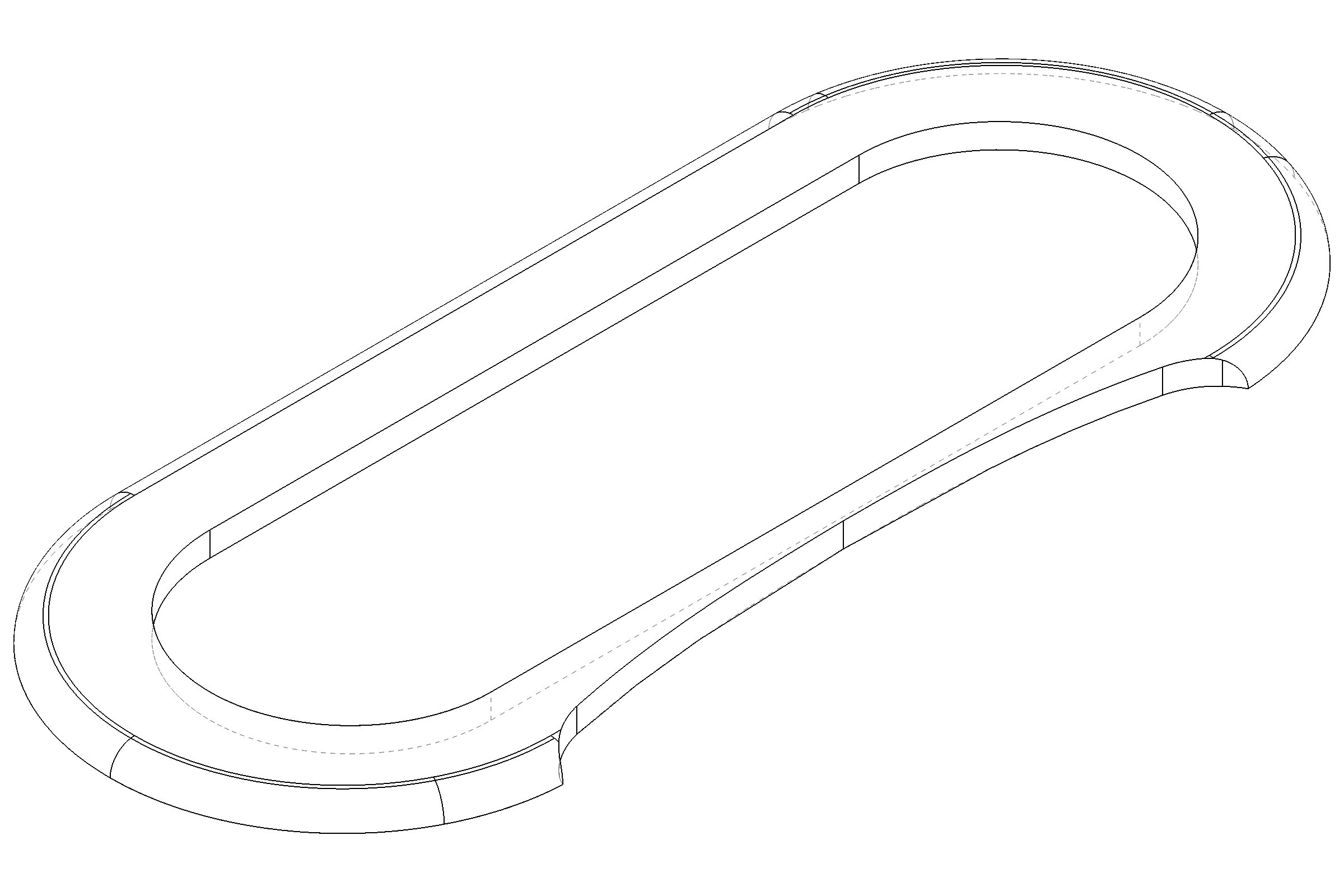
Included below are JPEG image files and PDF documents at 1:1 scale with line drawings of the pickguard, pickup surrounds, back plate and switch carrier plate. In the main image, the brown lines represent the cavity routing, the green line is the original Burns pickguard shape and the black line is my revised pickguard designs. You can download the watermarked 3D objects in STL format from my Thingiverse account:
https://www.thingiverse.com/dsguitarblog/designs
Important caveat: whilst I take a lot of care to ensure that my work is accurate for the job in hand, these drawings come with no guarantee that they will just drop onto any other Burns Brian May Red Special, or later BMG Specials. Cavity routing shapes and/or screw hole positions might have been changed between production runs so use my work only as a guide to save yourself some time and energy.

Next article:
Part 3: Routing and Milling Operations
Previous article:
Part 1: Inspection and Strip Down
