Preface
In 1963, because they could not afford to buy a suitable instrument, Brian and his father Harold took an innovative and practical approach to designing a new type of electric guitar. In the video below, I explore an urban myth in the Brian May Red Special enthusiast community that they drew around various household objects to form the basic outline and features of the guitar. Like all good urban myths, it might have an element of truth to it so watch the video, decide for yourself. then read on to get some insights into how I worked up my interpretation of the Red Special design in TurboCAD.
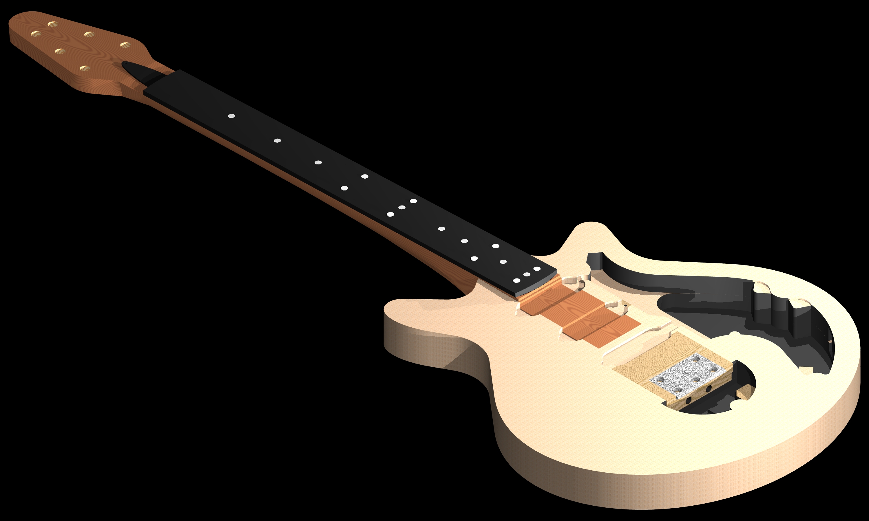
All components of this Red Special replica guitar that were required to be made on my CNC machine (body sections, neck, fretboard, upper oak insert, Bakelite nut, perspex pickguard set, aluminium switch frame and potentiometer/capacitor plate, aluminium roller bridge) or machined by third parties had to be reproduced in CAD and output as an STL file to be read into a CAM package (MeshCAM in my case) to create GCode toolpaths.
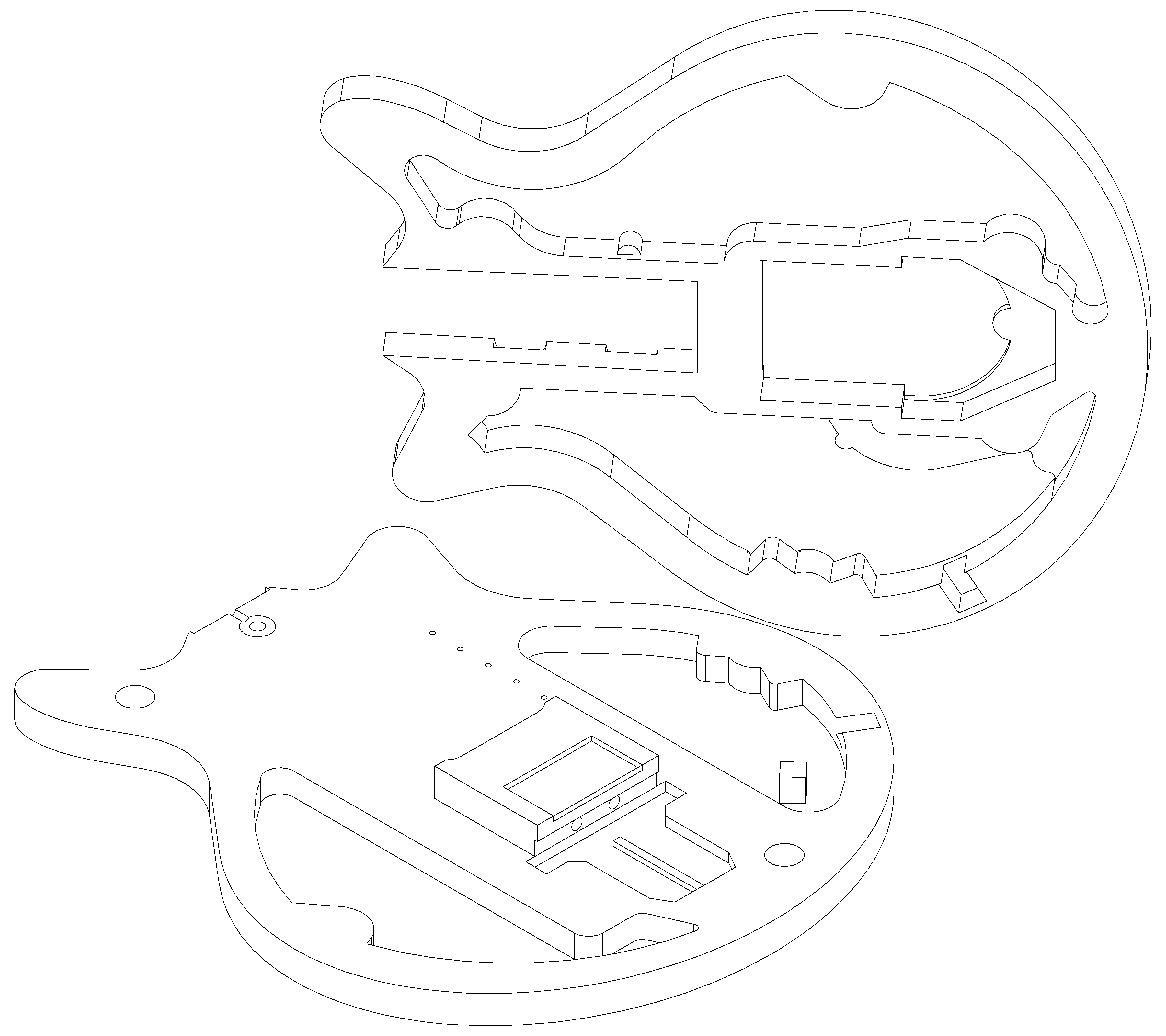
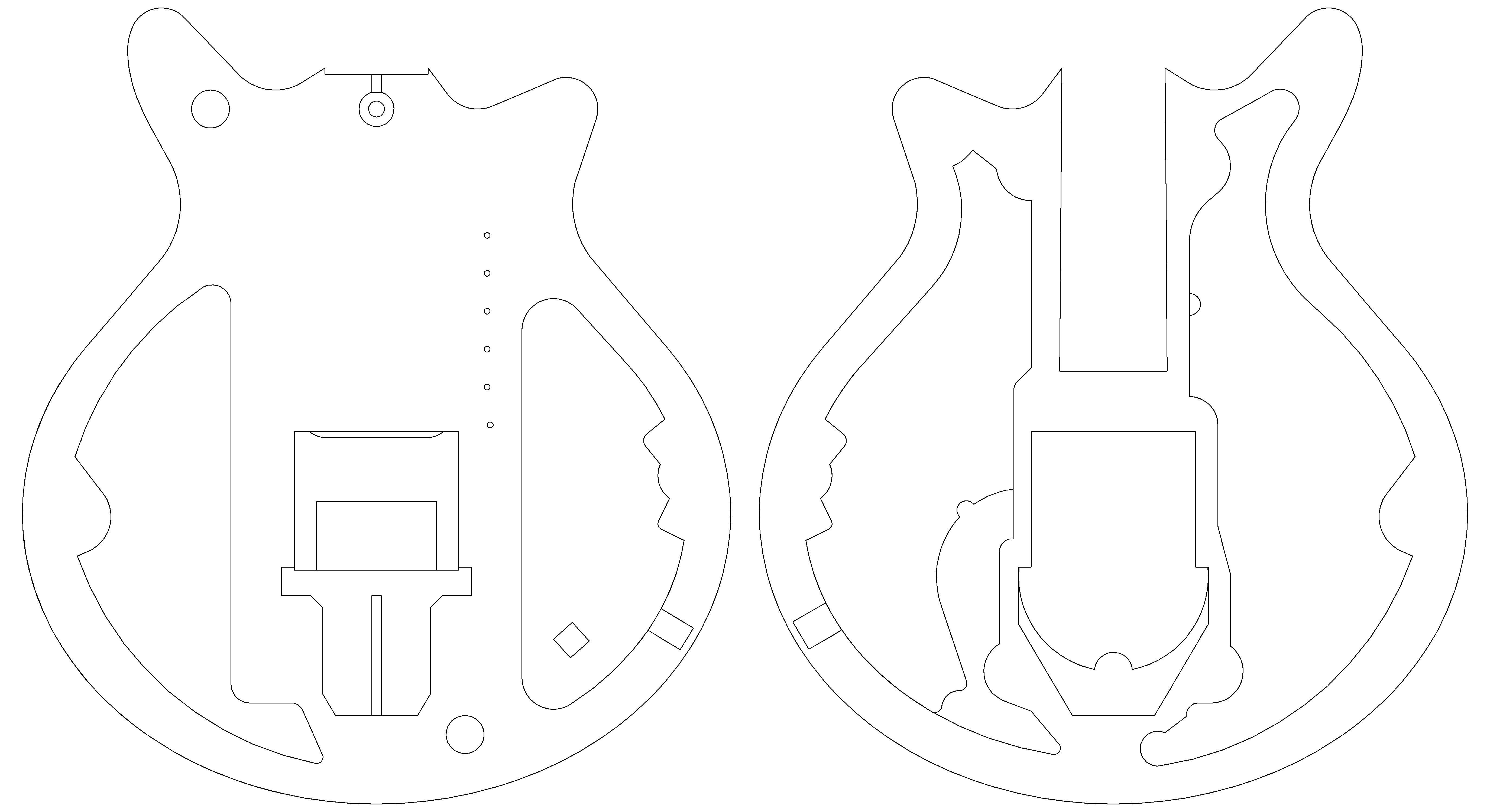
When the Red Special body shape 2D outlines were finalised, I moved on to working up 3D objects in TurboCAD. In a basic sense, this involves giving the 2D outlines depth and creating the cavities and rebates by adding and subtracting objects as required. In CAD/CAM jargon, simple 2D prismatic shapes with depth are referred to as “2.5D” objects (the guitar body sections in this case). Shapes such as the guitar neck with complex profiles in the Z axis (vertical directions) are genuine 3D objects. The four images in the gallery below are some renders of the final design from TurboCAD.


The Red Special Neck
In the first video of a series of two, I talk you through how I designed the neck for my Brian May Red Special guitar build using a CAD software utility. I begin by explaining how I worked up overall design sketches using known measurements and design details including the assumptions I made, then move on to cover the detail on the headstock, main section and tenon separately. I have illustrated this video with TurboCAD screen recordings and animated renders of the 3D objects.
The Red Special Body
In the second video on how I designed my interpretation of Brian May’s Red Special guitar from first principles, I explain how I created the overall shape and the internal details of the guitar body and pickguard. I have also illustrated this video with TurboCAD screen recordings and animated renders of the 3D objects in the same style as the previous video on the guitar neck.
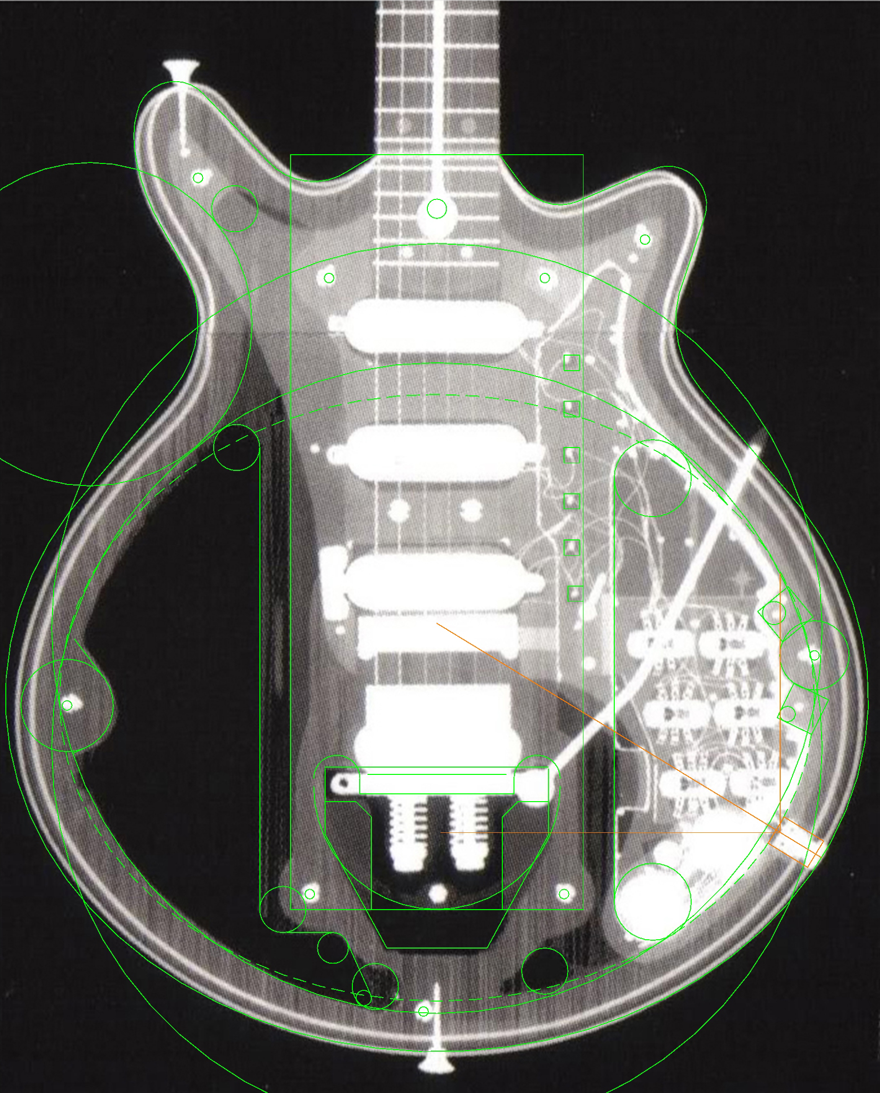
An important precursor to working up the Red Special body design in CAD is understanding the relatively complicated internal cavity structure of the guitar. Brian has stated that his goal was for the guitar to hold as much air as possible to allow it to interact with the amplified signal and feed back in a controllable way. He removed large proportion of the core softwood from the original blockboard using a wood chisel to form the acoustic cavity on the left/bass side of the guitar and a control cavity on the right/treble side of the guitar.
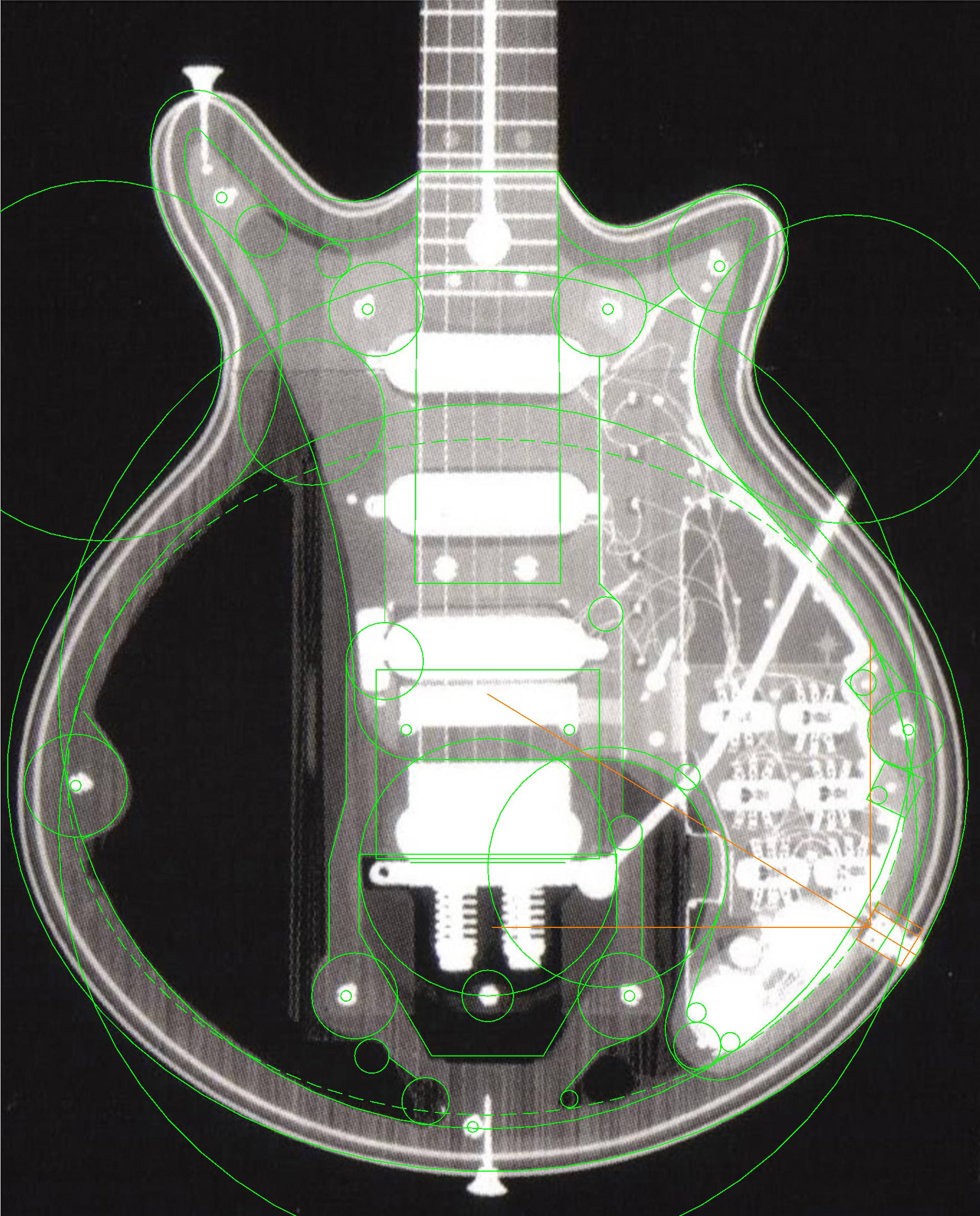
Although it is relatively well known that the Red Special construction uses oak and blockboard, X-ray images were taken in 2003 at St Bartholomew’s Hospital in London to allow its internal structure to be accurately determined for the Guyton authorised replicas. Presumably this was necessary because either Brian and Harold did not make detailed plans of the internal chambers, or that the end result differed significantly from the original design sketches due to cutting errors or ‘in field’ design changes which were not then reflected on the plans.
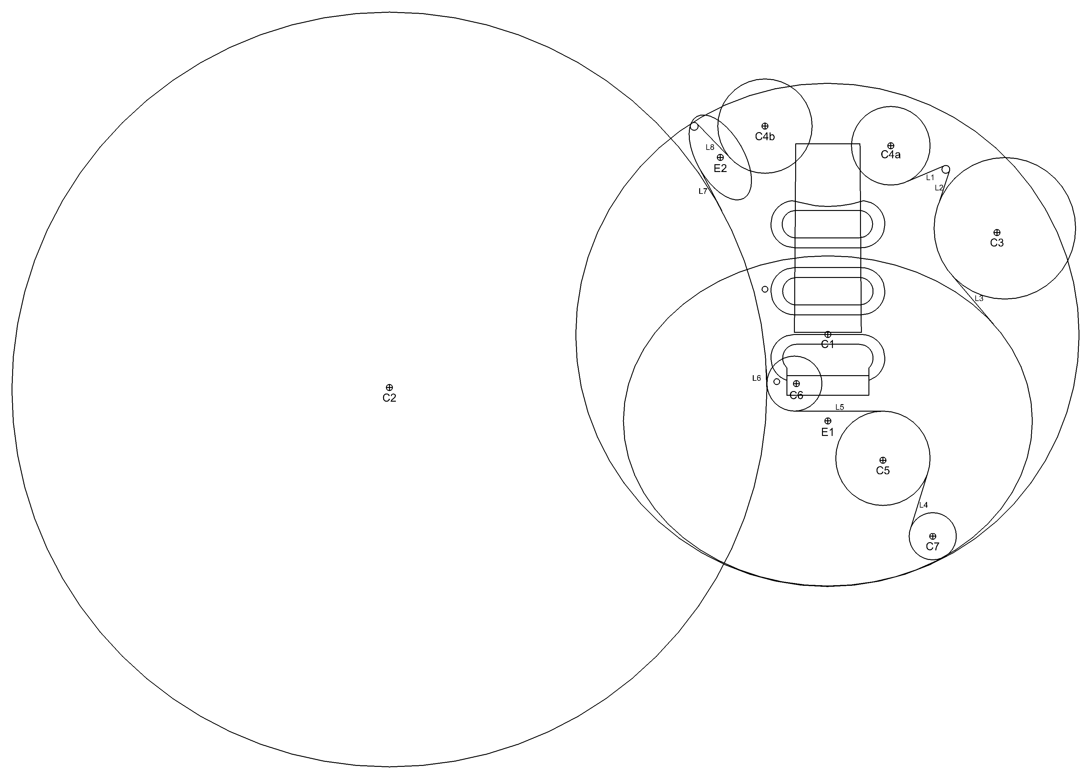
I therefore had to study the X-ray images and work up design sketches in the same manner as with the visible parts of the guitar body. The attached images illustrate the X-rays with construction lines drawn over them to form the cavities for the upper and lower sections and the design sketches I worked up from them. Note that the main body X-ray image is a montage of separate images that are pieced together. As a result, the features do not align well with the outline of the guitar and some educated guesswork was required on the position and size of the construction objects.
The Red Special Pickguard
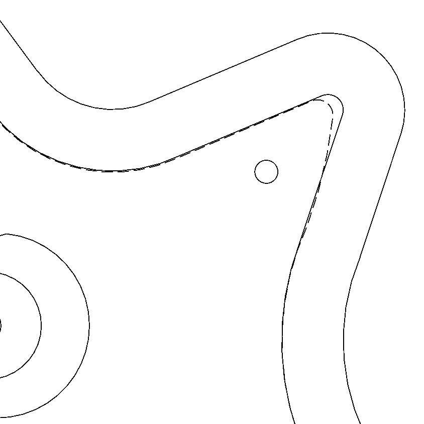
Moving forward to early 2016, after the shape fitting investigations on the Red Special headstock, I carried out an analogous study on the pickguard. It appears that the pickguard outer edge tracks the body shape with a gap of 1/2″ (12.7 mm) and, as with the headstock and guitar body, circles with regular imperial diameters were used to construct the curves and were joined up with either line segments or ellipse segments using a draughtsman’s French curve set. The sketch in the gallery below illustrates only the construction objects placed at the nearest 1/8″ locus as specified in the list below and labelled. The pickguard shape in the small horn region does not exactly fit the regular ‘theoretical’ shape I proposed and line segment L2 joining the tip to the cutaway curve is noticeably curved. Is it because the tip region was damaged during cutting and Brian had to slightly reprofile this area to smooth out the cutting error? Or was it designed like this from the outset?
Aluminium Sheet Parts
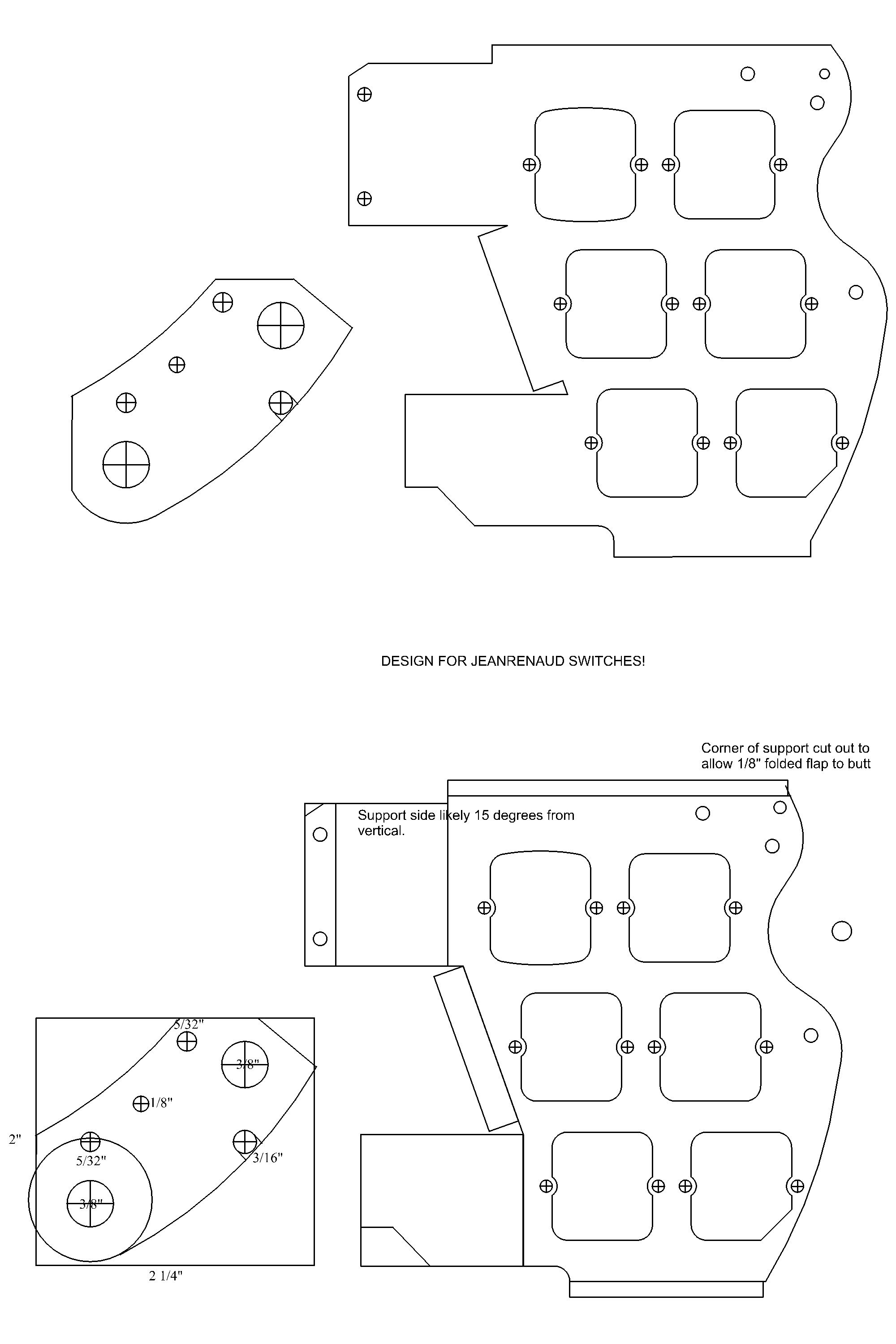
I spent a considerable amount of time working up and refining the design for the intricate aluminium switch frame and potentiometer/capacitor mounting plate. I bought a set of vintage Jeanrenaud DPDT parallel slide switches from French electronics enthusiast and Deacy amp expert, Manuel Angelini which allowed me to design the electronics system to match the size and shape of the original Red Special. The potentiometer and capacitor mounting plate required a degree of educated guesswork and at least four design revisions to get it anywhere near the same as the original due to the lack of revealing pictures on this piece.
The Red Special Hardware (Tremolo Block and Roller Bridge)
Although I was able to obtain authentic replica Red Special hardware, as an academic exercise to improve my CAD skills (part of the project philosophy), I worked up 3D CAD designs based on the intricate aluminium roller bridge, mild steel tremolo tail piece and knife edge fitted to the Guyton Brian May Red Special replicas. You might find it instructive to review the design drawings that Greg Fryer has published on his website: https://fryerguitars.wordpress.com/red-special-scratchplate-and-hardware/
https://fryerguitars.files.wordpress.com/2014/09/fryer-tremolo-tailpiece.jpg
https://fryerguitars.files.wordpress.com/2014/09/fryer-bm-trem-backing-plate-1.jpg
https://fryerguitars.files.wordpress.com/2014/09/fryer-bm-trem-backing-plate-2-final.jpg
https://fryerguitars.files.wordpress.com/2014/09/fryer-bm-trem-knife-edge.jpg
https://fryerguitars.files.wordpress.com/2014/09/fryer-tremolo-arm.jpg
https://fryerguitars.files.wordpress.com/2014/09/fryer-bm-bridge-drawing-fry-012.jpg
https://fryerguitars.files.wordpress.com/2014/09/fryer-bridge-george-burns.jpg
https://fryerguitars.files.wordpress.com/2014/09/fryer-bridge-roller.jpg
https://fryerguitars.files.wordpress.com/2014/09/fryer-bridge-roller-george-burns.jpg
https://fryerguitars.files.wordpress.com/2014/09/fryer-bm-trem-spring-brass-cup-holder.jpg
https://fryerguitars.files.wordpress.com/2014/09/fryer-bm-control-knob.jpg

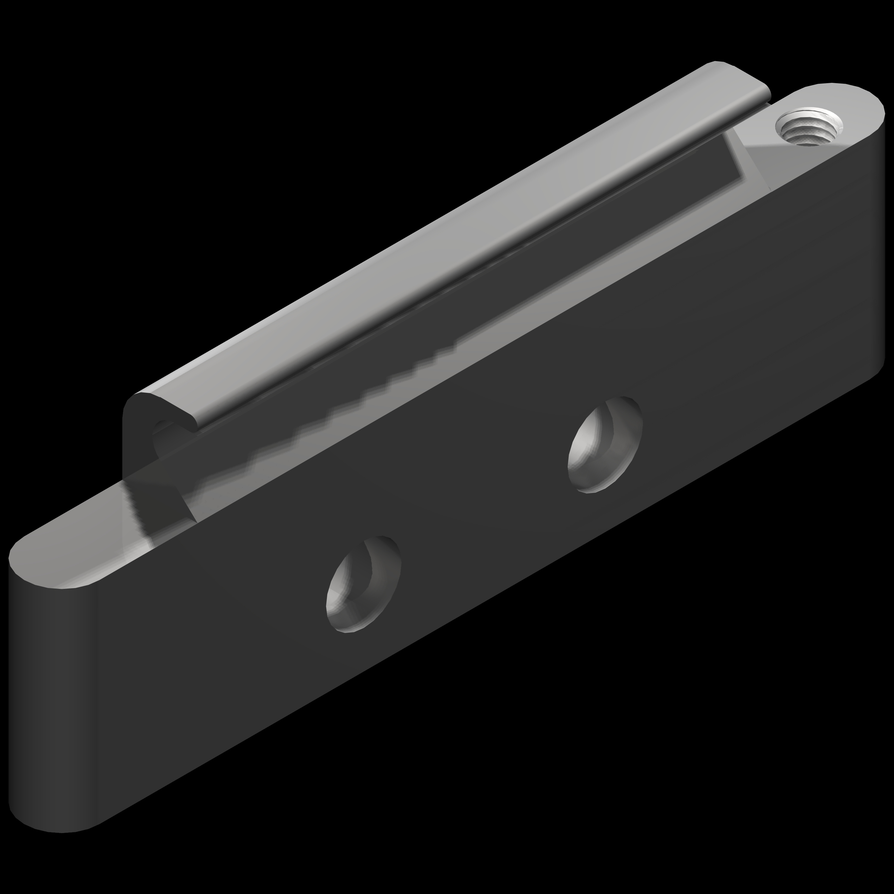
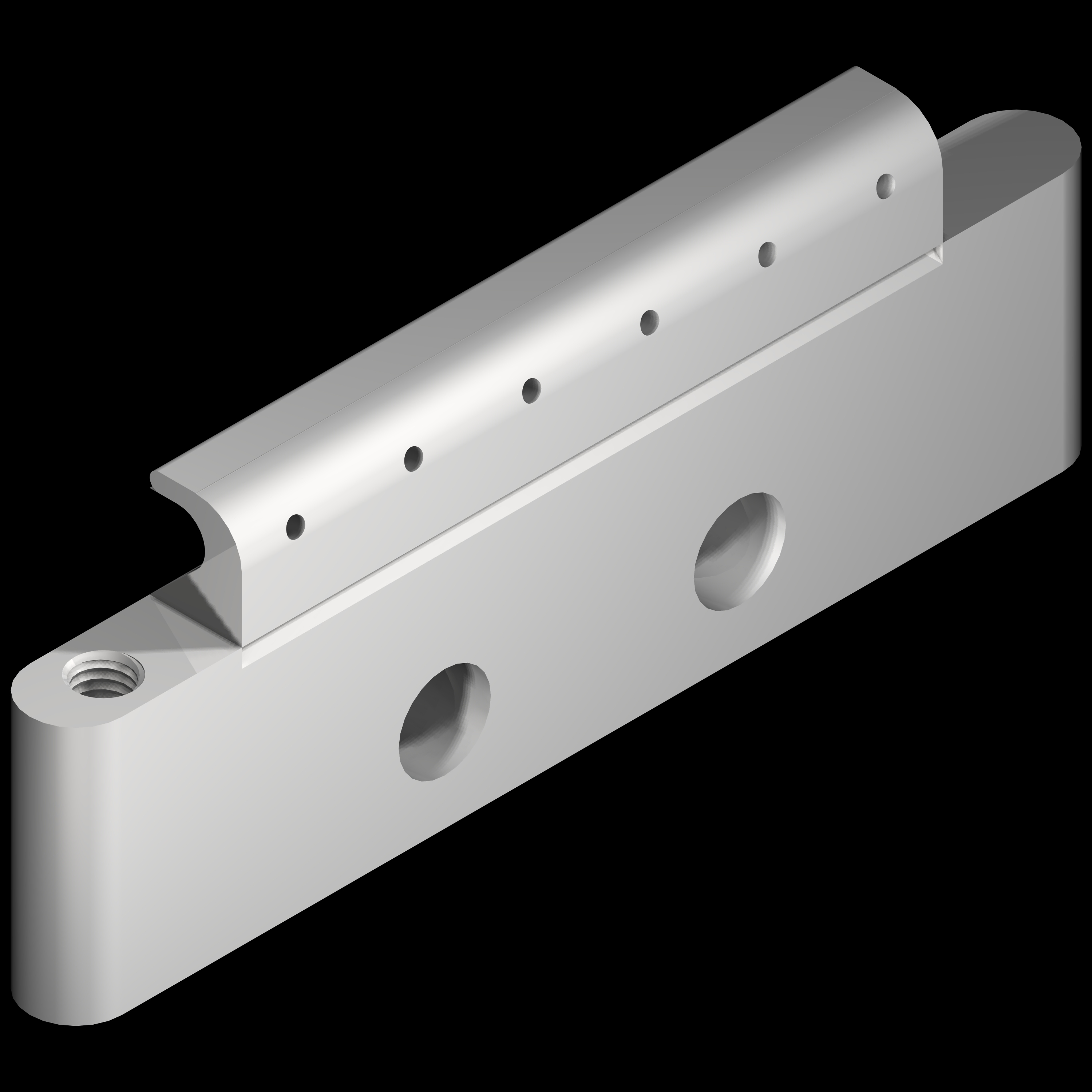

I revisited my CAD designs and CNC toolpaths in January 2022 and successfully milled a roller bridge from aluminium bar. I recorded all the stages and edited each segment to produce a 6m 50s YouTube video set to Brian’s guitar solo from A Night at The Odeon. The video description contains all the design dimensions of the aluminium blocks and stainless steel rollers and some essential information for milling aluminium on a hobby class CNC router (as opposed to a liquid-cooled CNC milling machine).
In autumn 2024 I fabricated a tremolo arm from scratch and filmed the processes for the YouTube video below which I released on 21 September 2024. It covers the design of the tremolo arm itself and the jig I made to form the three bends in the stainless steel rod section.
Return to the project home page:
https://dsgb.net/projects/redspecial/
Frequently Asked Questions
Brian May Red Special Guitar Build Project Design Sketches
