Component Selection
- The Switchcraft 46206LRX double pole, double throw (DPDT) switches with white actuators were sourced from AStrings and modified as pictured below to fit the available cavity space using a rotary multitool with diamond cutting wheel. Care was taken to avoid metal swarf entering the contacts and causing noise in operation.
- The Bourns PDB181-GTR02-254A2 rotary, 17 mm, plain shaft, audio (logarithmic) taper guitar potentiometers were bought in quantity from Farnell (order fulfilled directly from Bourns USA) and tested to obtain matched pairs at the nominal value of 250 kW using a Peak Electronics Atlas LCR45 passive component tester.
- A quantity of Vishay Roederstein 33 nF ±10% 200 V AC, 400 V DC through hole polyester film capacitors (part no. MKT1813333405) were obtained from RS Components and tested to find any with actual capacitances as close as possible to the original TCC Metalmite item (measured by Nigel Knight at 30.75 nF at 1 kHz and 20°C during a service of Brian May’s Red Special in 2013) using a Peak Electronics Atlas LCR45 passive component tester. One capacitor in the batch of 125 items ordered matched the advised value of the original to within ± 0.02 nF while the next closest match measured 30.89 nF at the reference conditions so this was used and the more closely matched capacitor retained for a future build project.


Switch Pack Wiring
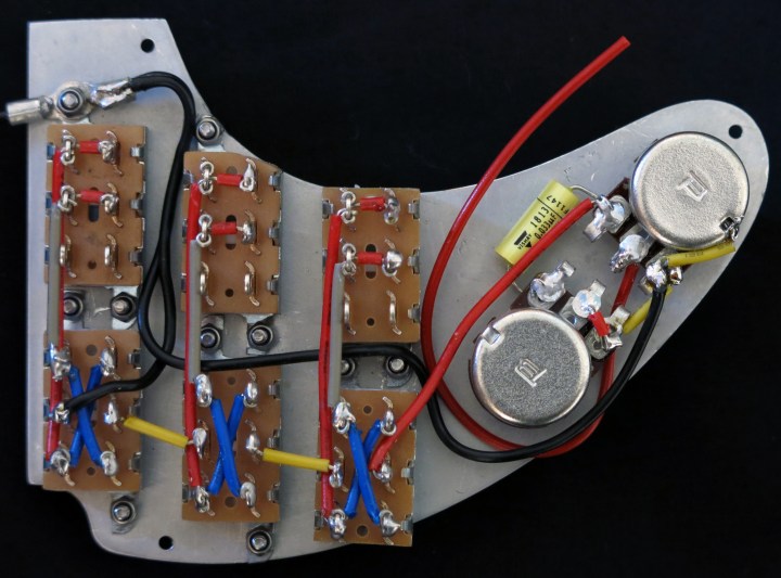
The switch pack wiring was assembled using the K&H jumper wire kit available from Rapid online:
https://www.rapidonline.com/k-h-ks-350-jumper-wire-kit-box-of-350-34-0495
I used this method later in my Fender Stratocaster conversion project and then re-purposed the electronics pack onto a Burns RS conversion here:
https://dsgb.net/projects/burns/part8/
A good mechanical connection was ensured by wrapping the wire ends through the lugs and back on themselves. The lug radius was sufficiently large to allow two jumper wires to be wrapped round and still have enough room for the pickup positive and negative wires to be placed through the centre and soldered. The assembly sequence was as follows:
- The six phase switch crossover links were connected using the blue jumper wires.
- The three [on/off switch middle to phase switch inboard] links were connected using the grey jumper wires.
- The three [on/off switch inboard to phase switch outboard] links were connected using the longer of the red jumper wires.
- The six on/off switch contact redundancy links were connected using the shorter of the red jumper wires.
- The two interlinks between the three phase switch middle lugs were connected using the yellow jumper wires.
- The potentiometer tabs were bent back on themselves to allow sufficient room for the potentiometers to be mounted with the tabs directly opposing each other thus allowing room for the capacitor to be located at one side.
- The potentiometers were mounted on the control plate with a securing nut underneath to reduce the overall height of the shaft above the pickguard since only 11 mm was available in the control knob to accommodate the shaft and upper securing nut.
- A long red jumper wire was connected between the bridge pickup phase switch spare lug to the volume potentiometer inboard tab.
- The capacitor was connected between the tone and volume capacitor inboard tabs.
- A length of red multistrand copper equipment wire (Maplin code FA33D) was soldered to the volume potentiometer middle tab which will be connected to the jack socket tip terminal (the jack socket barrel terminal is earthed with a short length of black multistrand copper equipment wire (Maplin code FA26D) to the control cavity copper shielding).
- Common grounding connections were prepared as follows:
(a) Between the two unused tabs of the tone potentiometer using a small red jumper wire
(b) Between the two outboard tabs of the tone and volume potentiometers using a yellow jumper wire
(c) Between the outboard tab and the body of the volume potentiometer using a yellow jumper wire
(d) A length of black multistrand copper equipment wire was soldered on to the outboard tab of the volume potentiometer
(e) A second length of black multistrand copper equipment wire was soldered to the neck pickup phase switch spare lug.
(f) A third length of black multistrand copper equipment wire was terminated in a solder tab at both ends to form the control plate final grounding connection to the control cavity copper shielding - The two lengths of black multistrand copper equipment wire formed in operations 11 (d) and (e) were run through the switches and terminated in a single solder tab.
- The two lengths of black multistrand copper equipment wire formed in operations 11 (f) and 12 were connected to inboard mounting screw of the neck pickup’s on/off switch.
- The jack socket (a Switchcraft long barrel mono item) was positioned with the tip arm at the bottom of the control cavity and the two tabs uppermost to afford the most room for the potentiometers without risk of shorting out and was secured in place with the ¼ inch (6.35 mm) nut. This required a piece of electrical insulating tape to be placed between the tip arm and the copper control cavity shielding to prevent shorting out.
- The exposed multistrand wire ends of the three pickup body earthing wires (green insulation) were twisted together and terminated in a common solder tab for connection to the common ground on the control cavity copper shielding.
- Each individual pickup’s pair of positive and negative wires were twisted together and the ends secured with a length of black heat shrink material to prevent them unwinding. (The number of twists per unit length in the original instrument’s wiring is not known but can be seen in Greg Fryer’s 1998 restoration photographs).
- The final connections were made by soldering the pickup connection wires on to the on/off switch contacts, securing the control plate earth wire and pickup body earth wire tabs to the shelf in the control cavity using a brass screw. The brass screw, copper and jack socket solder tabs were all abraded with 800 grit wet and dry paper then degreased to ensure good electrical contact.


General Notes
A high lead content multicore solder (RS Components item code 555-235) was used for all electrical connections, including the solder beads around the seams of the control cavity copper sections on the recommendation of Nigel Knight because of its low melting point (183-188°C) and good quantity of flux in the cores. A soldering iron temperature of 250°C was used for the electrical connections and 300°C for the solder beads around the copper cavity sections. Additional rosin–based liquid flux was applied to the connection via a flux pen. Isopropyl alcohol (IPA) was used to degrease all items prior to fluxing and soldering.
Next article:
Part 7: Test Assembly
Previous article:
Part 5: Aluminium Control Plate
