A neat solution to eliminating the visible screws on top of the pickguard that secure the parallel slide switches was originally suggested to me by Nigel Knight for my Stratocaster conversion project. It involves a custom made CNC cut perspex plate which has brass M3 threaded inserts thermoset into it. The plate is then glued onto the underside of the pickguard, ensuring that the apertures in both pieces align precisely. On the Stratocaster project, the plate carried a custom made PCB with miniature pushbutton switches which Nigel modified from the Guyton RS Transporter design. The PCB was mounted with standoffs made from short sections of PTFE rod.
The embedded video below illustrates the three stage process of thermosetting the inserts into the perspex. All the apertures and pilot holes for the inserts are cut by CNC to ensure that they are situated precisely.
The initial holes were CNC cut to 1/8″ (3.2 mm) diameter. After holding the carrier plate down on my drill press bed with double sided adhesive tape, I locate the hole using the 1/8″ drill bit, then I swap to a 3.5 mm drill bit and open out the hole. Next I insert a length of M3 stainless steel machine screw with the brass threaded insert on the end. I heat this using an electric heat gun and slowly press it into the 3.5 mm hole.
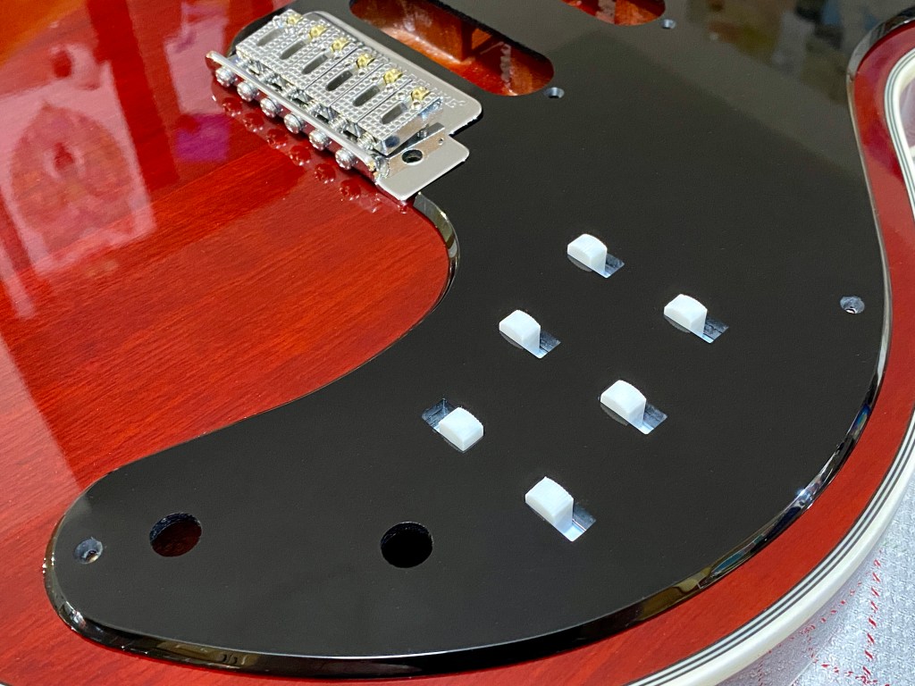
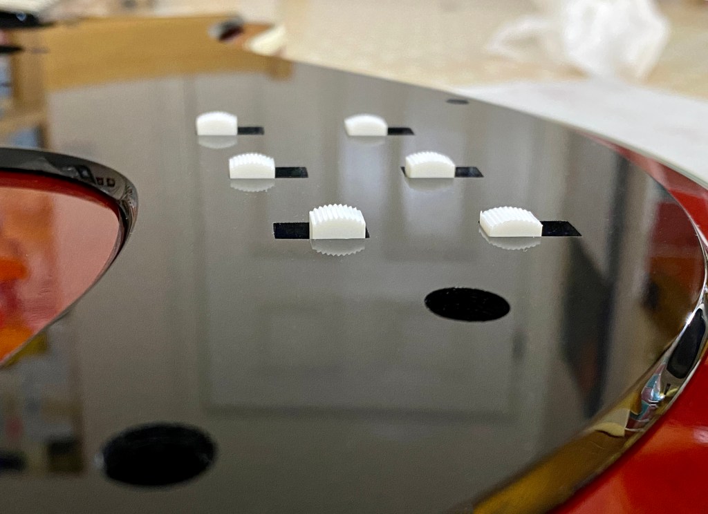
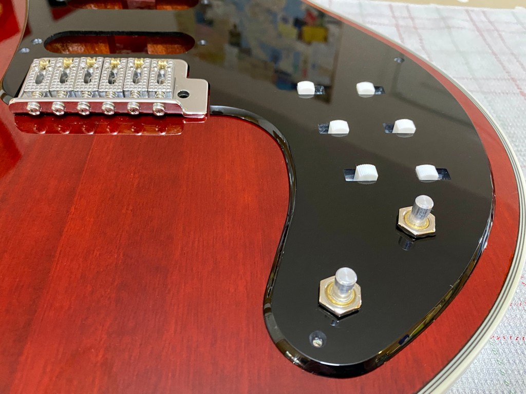
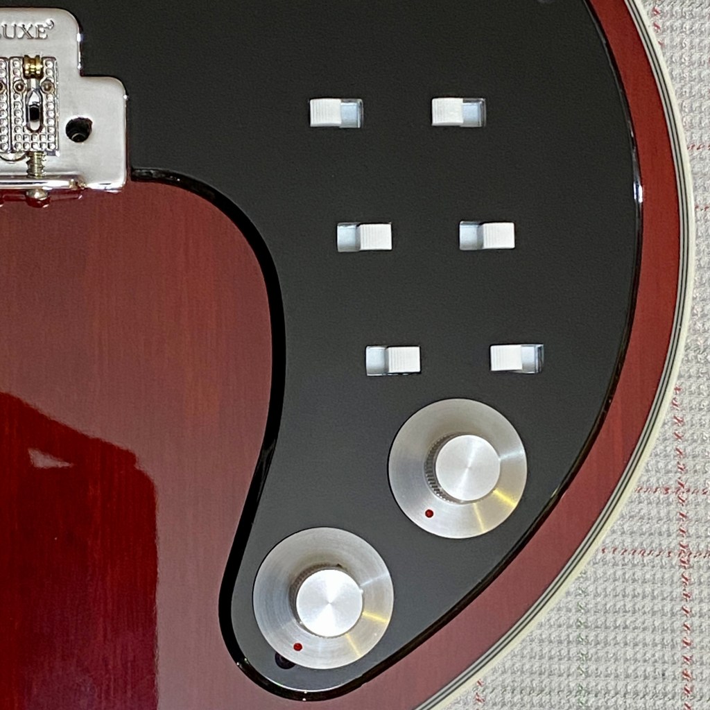
In this case, I cut the carrier plate from the same 3 mm thick black perspex I made the main pickguard from. I overlapped the middle screw holes in the switches so that nine M3 thread inserts were required. For this project, I re-purposed the electronics assembly I made for an early variant of my Brian May Stratocaster pickguard. If I had started with new components, I would have cut the mounting lug of each switch down the screw hole centreline so that it could be mounted without overlapping the adjacent switch. The overlap is barely noticeable, either visually or in operation when switching, as you can see in the close-up photographs below.
I reduced the height of the brass inserts using a diamond cutting disc prior to insertion and milled the inserts down after installation flush with both surfaces prior to gluing. This was necessary because they were still slightly thicker than the 3 mm perspex sheet and the plastic melts during thermosetting and piles up around the insert.
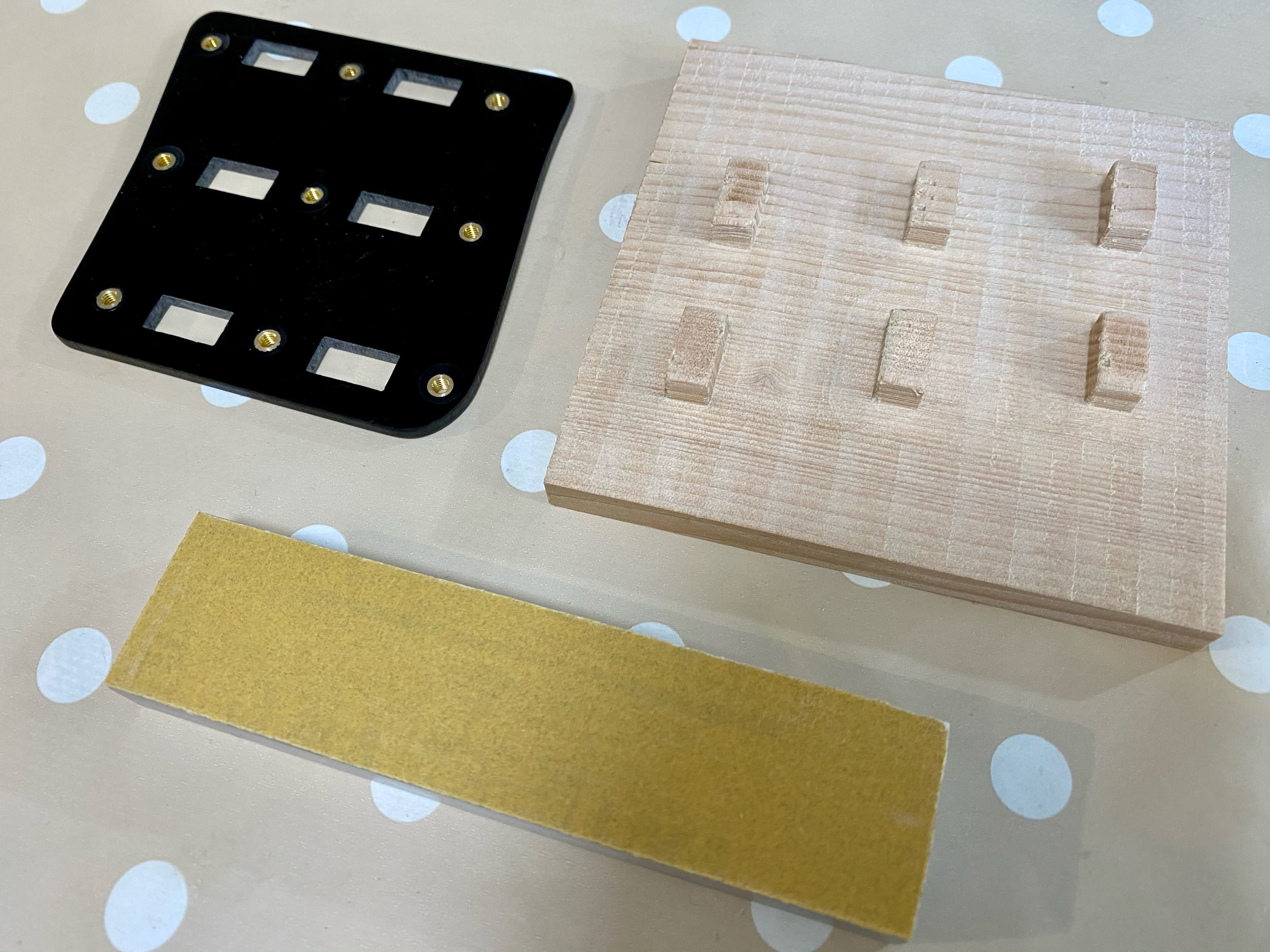
Since precise alignment of the switch holes is desirable and gluing with superglue allows no margin for error, I designed and CNC-cut an alignment jig from a block of offcut spruce I used in the core of the blockboard for my Brian May Red Special build. This worked well.


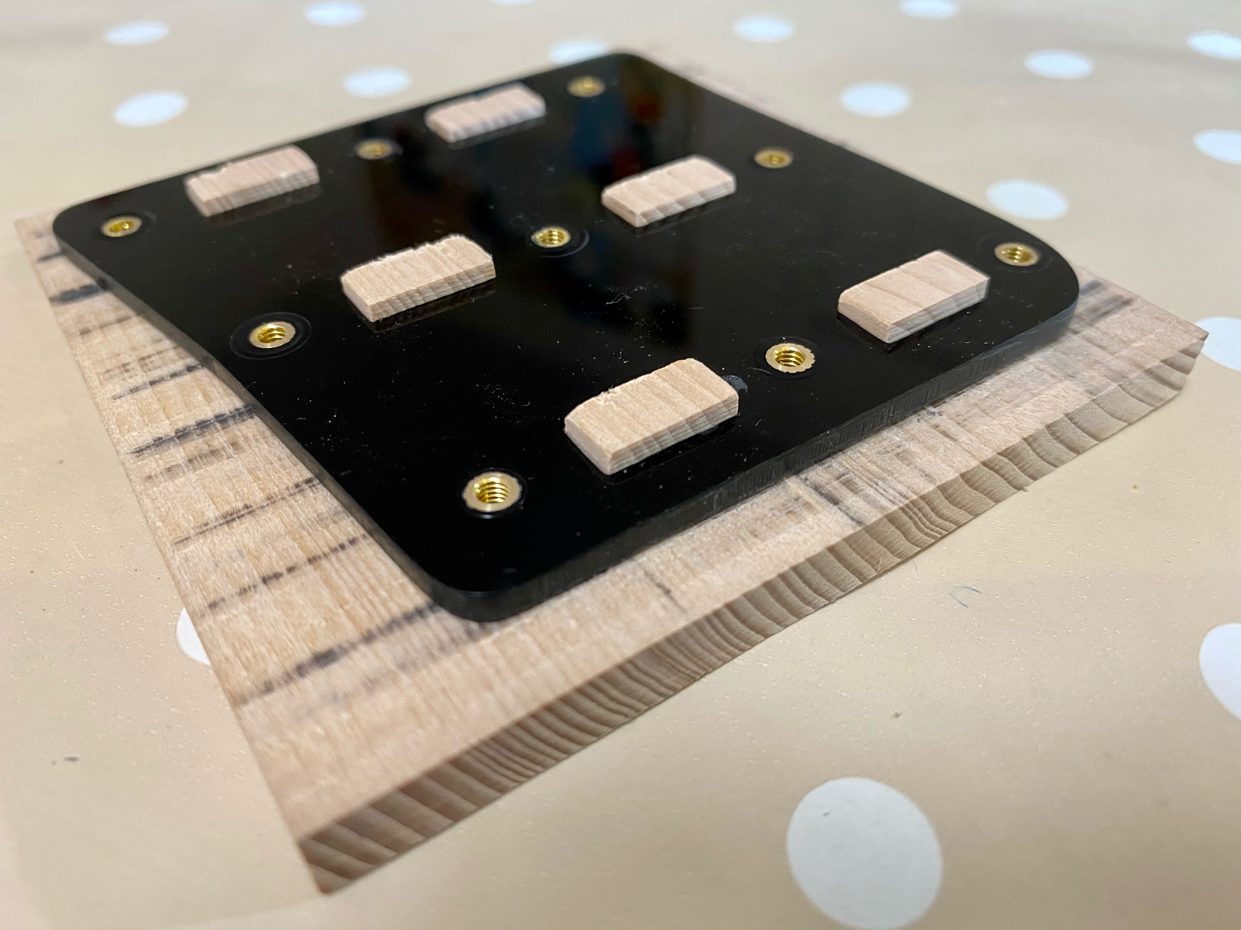

I then mounted the switch pack onto the carrier plate and repeated the pickguard fit test as illustrated in the pictures in the next gallery.


Next article:
Part 6: Mechanical Set-up
Previous article:
Part 4: Pickguard Fit Tests
