With the body and neck married together successfully, I then drilled the various screw pilot holes, access holes and rebates in the Brian May Red Special guitar neck and body. This could have been done after the lacquer finish was completed but I wanted to do it at this stage in case repairs were required since it can be quite challenging to execute to a high standard without access to specialist workshop equipment.
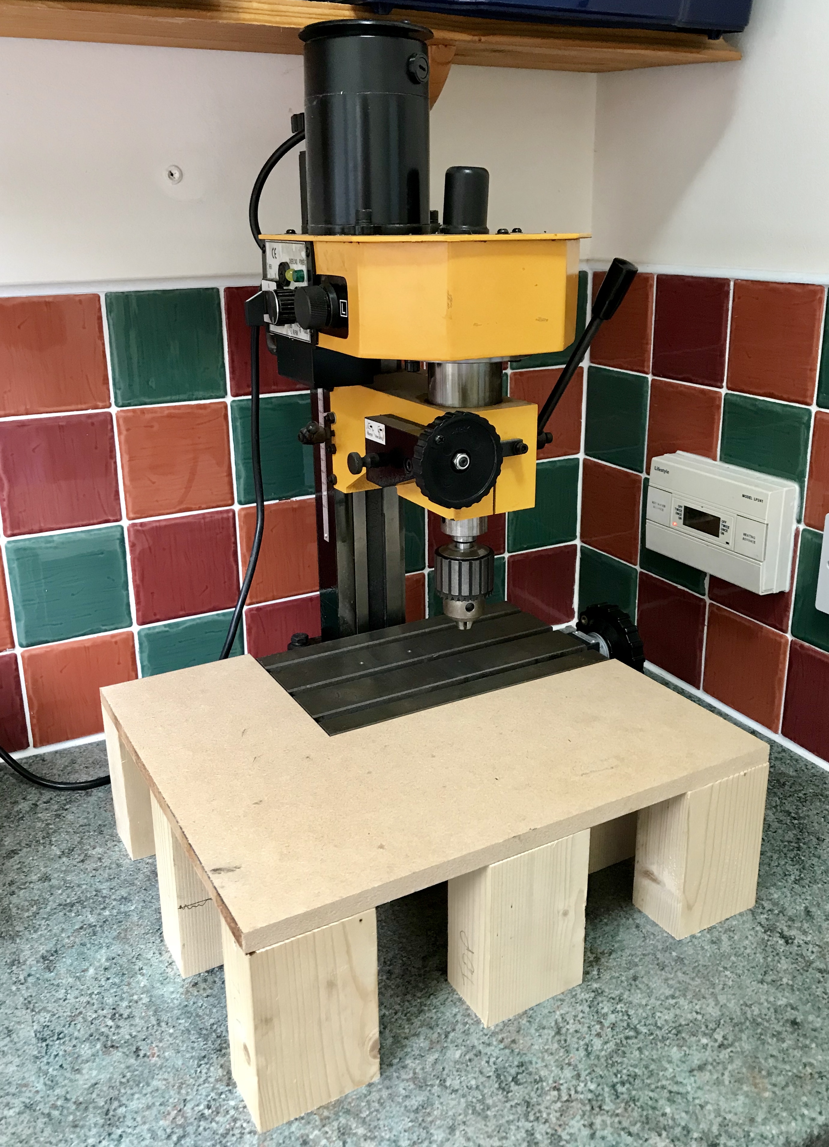
The first preparatory task I undertook was to make a plinth to extend the bed size of my Clarke CMD10 micro milling/drilling machine to around 12″ x 14″ so that the guitar body could be fully supported. I cut this from a sheet of the 12 mm thick MDF sheet I use for CNC machine spoil boards and some spare PAR white timber using my Makita 2704 table saw. The bed surface is 4 13/16″ (122 mm) from the base so care was required to cut the timber accurately to 4 11/32″ (110 mm) high. There was no particular requirement to glue or screw this together into a single assembly but to discourage movement during drilling and to protect the guitar body veneer, I placed a thin (1.2 mm) silicone mat on top of it.
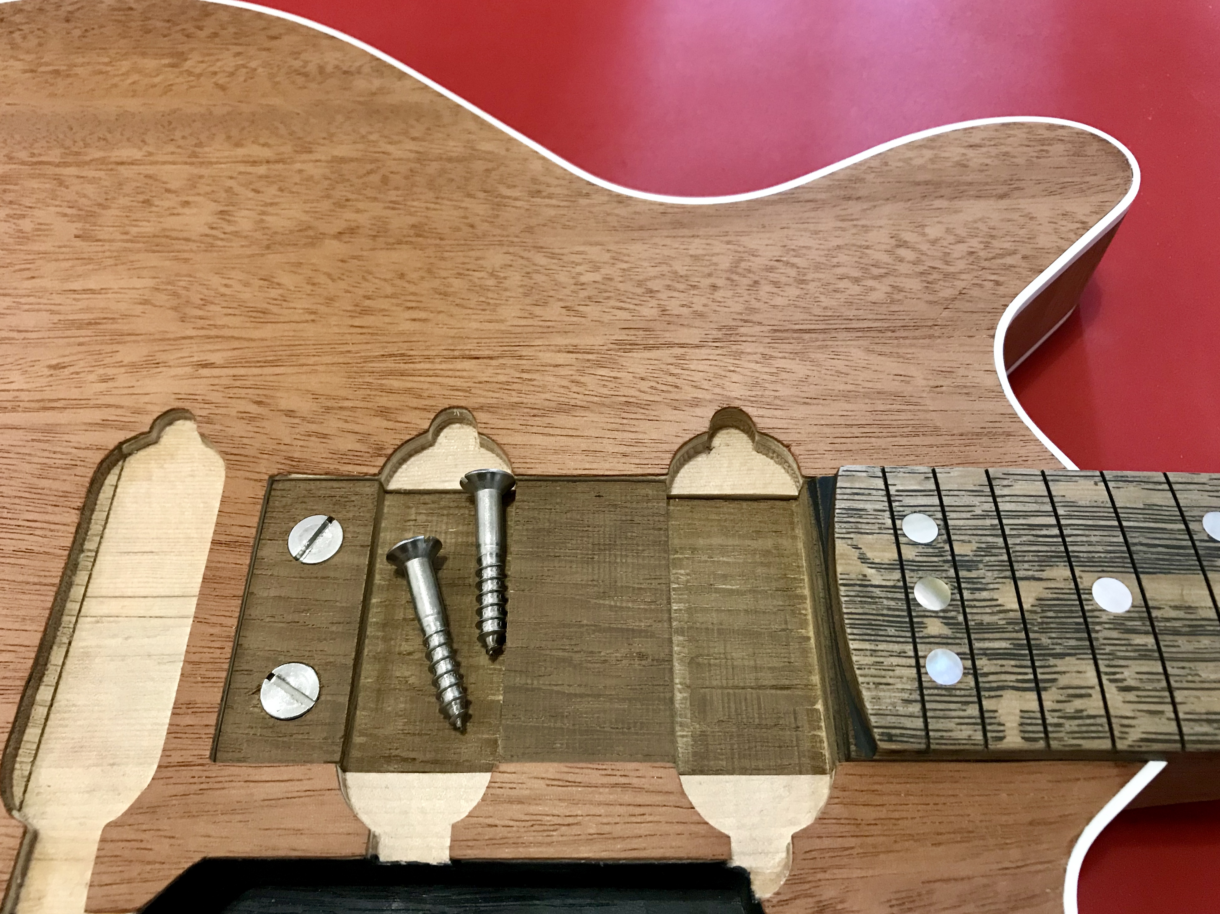
Next, I drilled the pilot holes in the neck tenon and guitar body to accept two No.12 x 1 1/4″ slotted countersunk wood screws which is my estimate for those used on the original guitar. I have found that modern metric equivalent screws can be a few millimetres short of the nominal imperial size and in this case I used 1 3/8″ (35 mm including the head) length screws to mitigate this issue. I used four drill bits for this procedure: a 1.0 mm bit to locate the chuck to the centre spot then a 3/16″ bit to drill the pilot hole for the threaded section of the screw, a 7/32″ (5.5 mm) bit for the larger diameter plain upper section and finally a 13/32″ (10.3 mm) bit to drill the countersink.

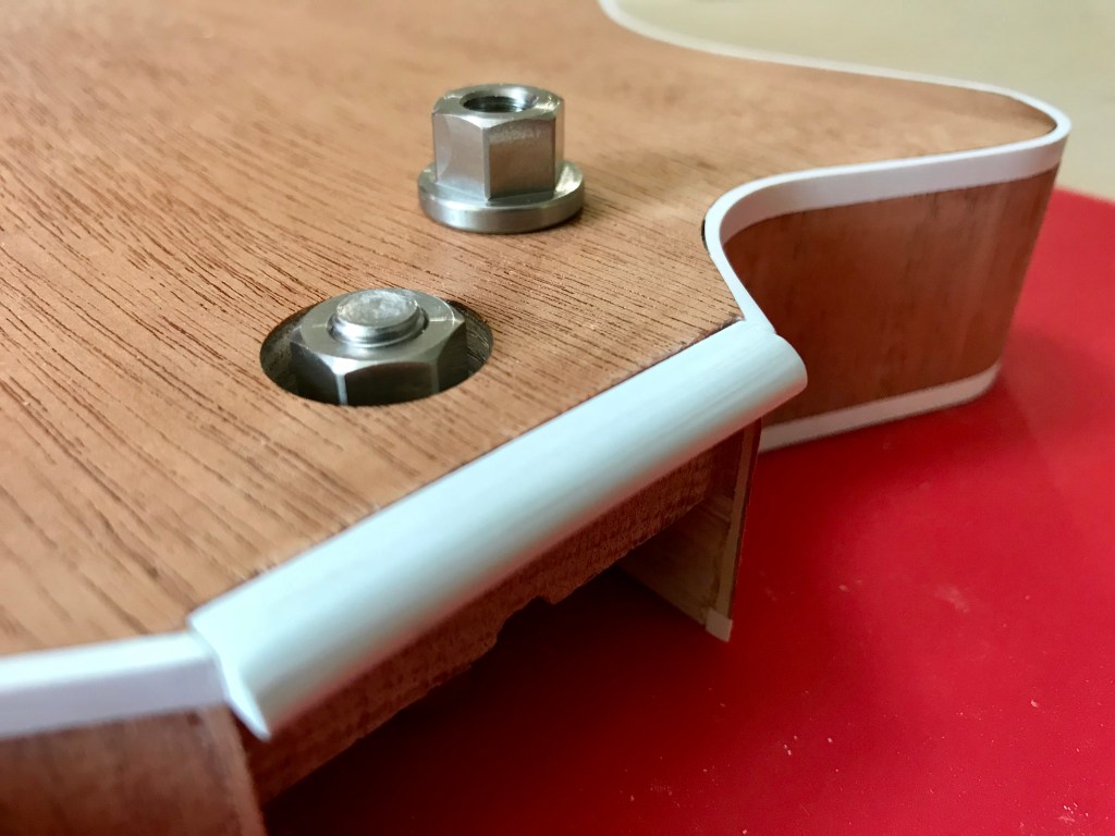
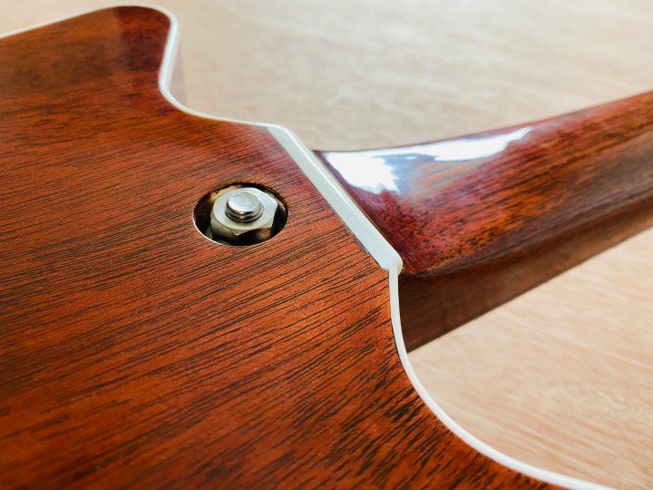
Moving on to the guitar body rebates and access holes, I first drilled the rebate for the nut that secures the neck bolt. I judged this to be 3/4″ diameter since this looks correct from pictures of the original guitar and it allows a socket for a 1/2″ wide nut (across the flats) to be used to tighten the nut with minimal sufficient clearance. One cosmetic feature of the original guitar I wished to replicate is the protruding bolt and nut but due to an oversight when assembling the neck, I fitted a bolt which was substantially too short (1 1/4″ compared to the original which appears to be around 1 1/2″ to 1 5/8″) therefore I had to come up with a workaround.
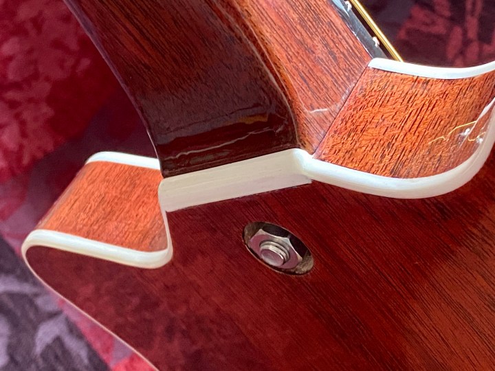
The rebate had to be drilled to 3/8″ deep to allow a 5/16″ UNF half nut and thin washer (5.8 mm total thickness) to fully engage the available bolt thread so I committed to this. I found a U.K. supplier of billet CNC cut stainless steel 5/16″ UNF thread nuts with a thick flange and extra long hexagonal section intended for vintage motorcycles. Thankfully this does a great job of filling the inappropriately deep rebate. I will need to cut a short length (approximately 1/4″) of threaded bolt to fill the remaining thread plus some protrusion which I will secure in place with threadlock adhesive. One of the pictures in the gallery illustrates the intended final appearance with one of these larger nuts in full view.
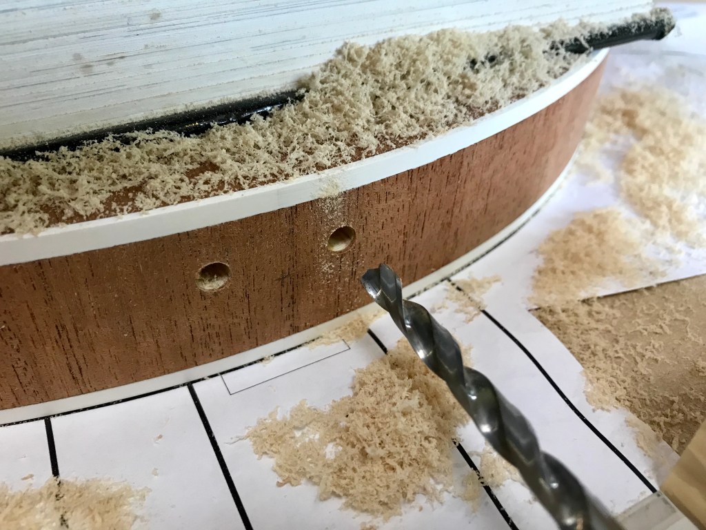
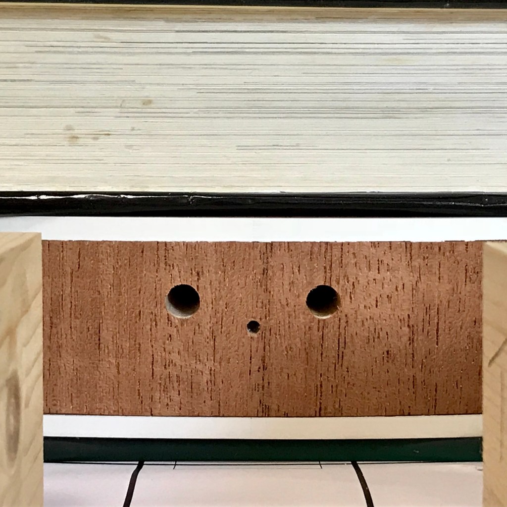
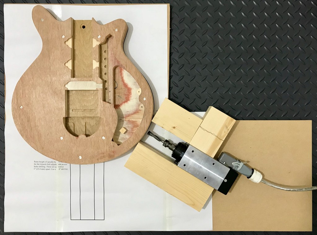
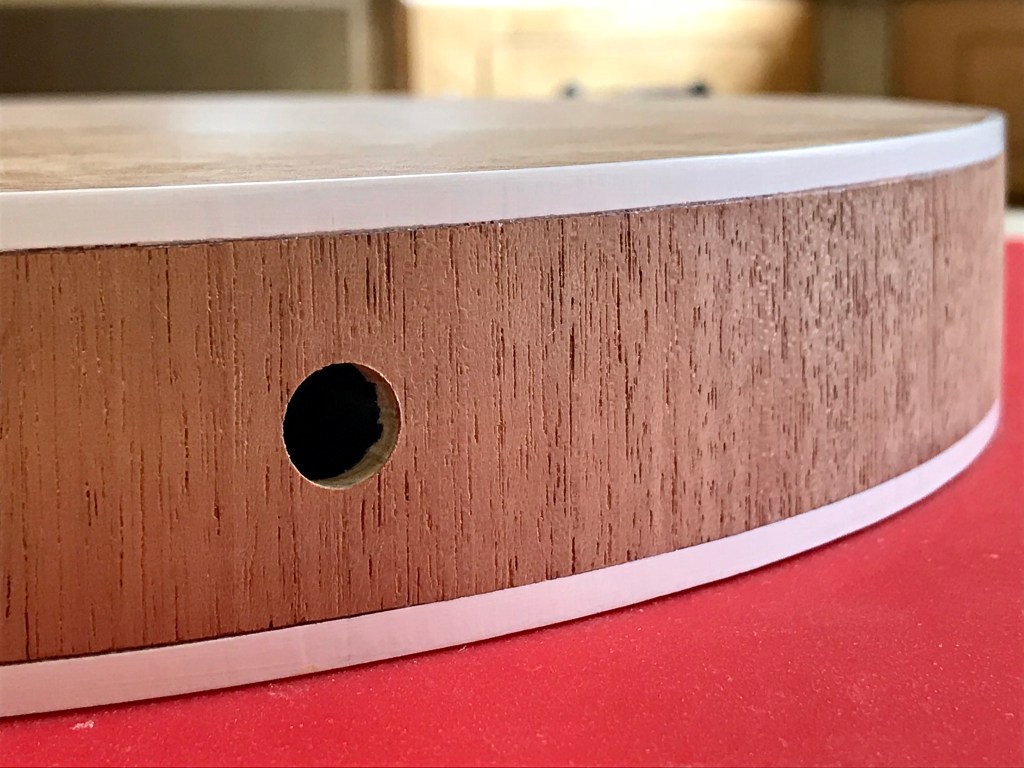
Learning from the experience of building a 3/4 scale Red Special in 2013/14, I planned to use the small HF industrial milling spindle from my CNC outfit as a horizontal drill to drill the jack socket hole and tremolo bolt adjustment access holes because it has a cuboid aluminium body and can be laid flat on a worksurface with sections of PAR white timber as guide rails. This setup is illustrated in the picture gallery. I struggled to do this accurately on the 3/4 scale Red Special build because I had no means to drill the holes with the guitar oriented vertically and only a standard cordless Makita drill and a Dremel multitool with which to attempt a horizontal drill. I achieved a reasonable result by attaching guide bars made from strips of PAR timber with Duck tape to the Makita cordless drill which, like every other type, does not have a flat top surface.
I wanted to do a better job this time so I resolved to use the small industrial HF milling spindle from my CNC outfit which, helpfully, does have a cuboid body with four flat sides, in conjunction with PAR white timber guide rails taped to a board. I drew up a 1:1 scale drilling diagram in TurboCAD and printed it out on several sheets of A3 paper which I matched up and taped together. Sometimes you just have to do things the same way Brian and Harold did many decades ago. I placed the guitar body on the diagram, weighted it down with many cookery books, carefully lined up the milling spindle using a 0.8 mm diameter end mill for locating the centre spot accurately and cut up a laminated place mat to shim the spindle to the correct height before carefully drilled the holes.

Next article:
Part 49: Neck and Fretboard Finishing Preparation and Re-Work
Previous article:
Part 47: Marrying the Body and Neck
