I originally intended to carry out a straightforward, inexpensive and fully reversible modification to my 2012 Fender American Standard Stratocaster that retained the original instrument’s appearance as far as possible. I planned to use materials and components I already had available; these included 3 mm thick black Perspex sheet, six Switchcraft 46200LRX series DPDT parallel slide switches, two Bourns PDB181-GTR02-254A2 potentiometers, a 30 nF polyester capacitor and solid core jumper wires to connect the electronics. I had previously fitted three Burns mini Tri-Sonic pickups to my 3/4 scale ‘1975’ Red Special replica and these had offered a satisfactory tone, so I bought another set direct from Burns London in February 2018. I discuss the pickups in the next article.
OEM Pickguard and Cavity Shape Assessment
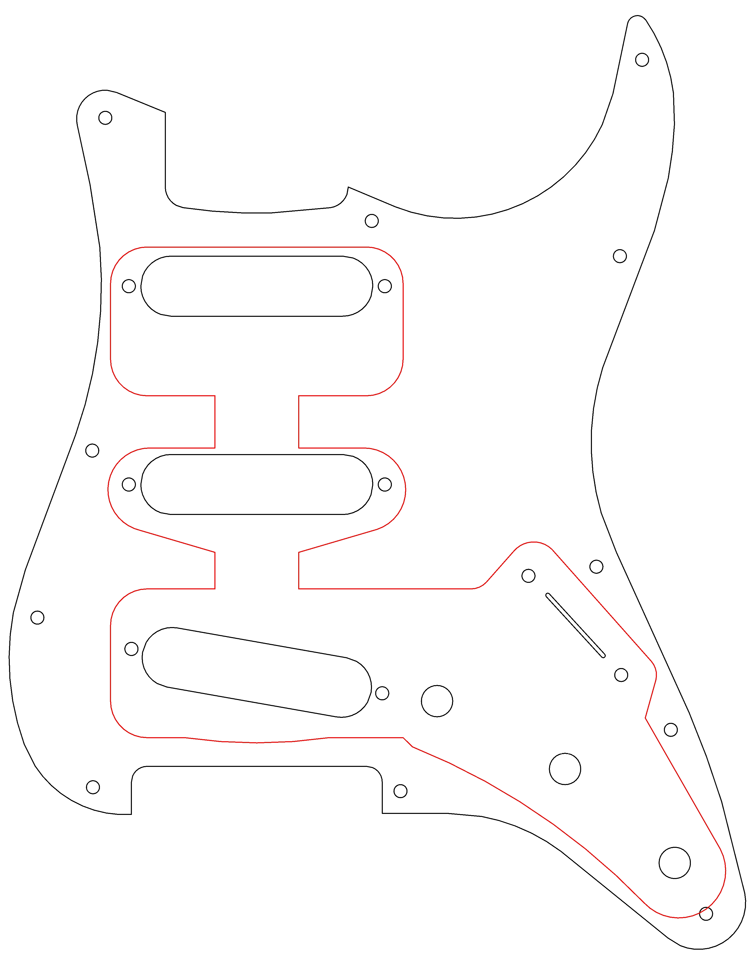
Since I described the process of transferring the cavity shape from the guitar body to TurboCAD in my Burns conversion article in some detail, I will not repeat the process here. However, to summarise, I dismantled the instrument then scanned the pickguard set on an A4 flatbed scanner with an engineering ruler to facilitate scaling of the image in TurboCAD. After importing the scanned image into TurboCAD and adjusting them to 1:1 scale, I constructed the pickguard and back-plate shapes by overlaying circles corresponded to the arc radii and line segments onto the image noting that because the Fender Stratocaster was designed in the 1950s, the radii of the circles correspond to imperial dimensions. The image gallery and attached PDF files below illustrate the original pickguard shape overlaid with the cavity and then the proposed revised pickguard with full size Burns Tri-Sonic pickups and switches overlaid.
The first challenge was to assess whether it was possible to fit full size Burns Tri-Sonics and the Switchcraft switches into the available space. I did not wish to drill or rout the existing cavity to preserve the body of the instrument in original condition. As you can see from the sketch below, this was indeed achievable but I had to clip the ends of the pickup mounting tabs and overlap the central screw holes of each bank of switches.


KAT Guyton RS Transporter Style PCB Electronics
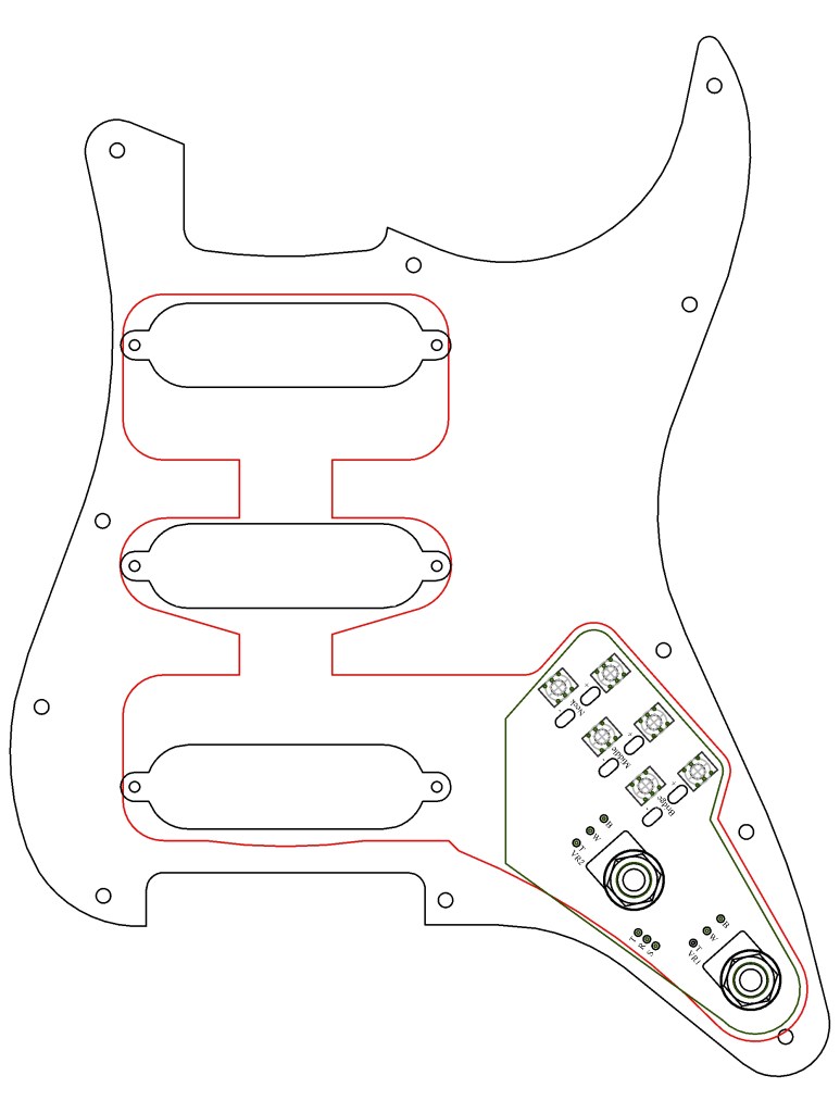
As the project progressed, Nigel Knight of Knight Audio Technologies (KAT) offered to modify his design for the Guyton RS Transporter printed circuit board (PCB) which uses six pushbuttons in place of the six parallel slide switches. The size and shape of the PCB was designed to fit neatly into the Stratocaster cavity and achieve a spacing between the volume and tone control knobs that was similar to the original Red Special. This is illustrated in the image gallery below together with the revised pickguard design.
Design Sketches in Adobe PDF File Format
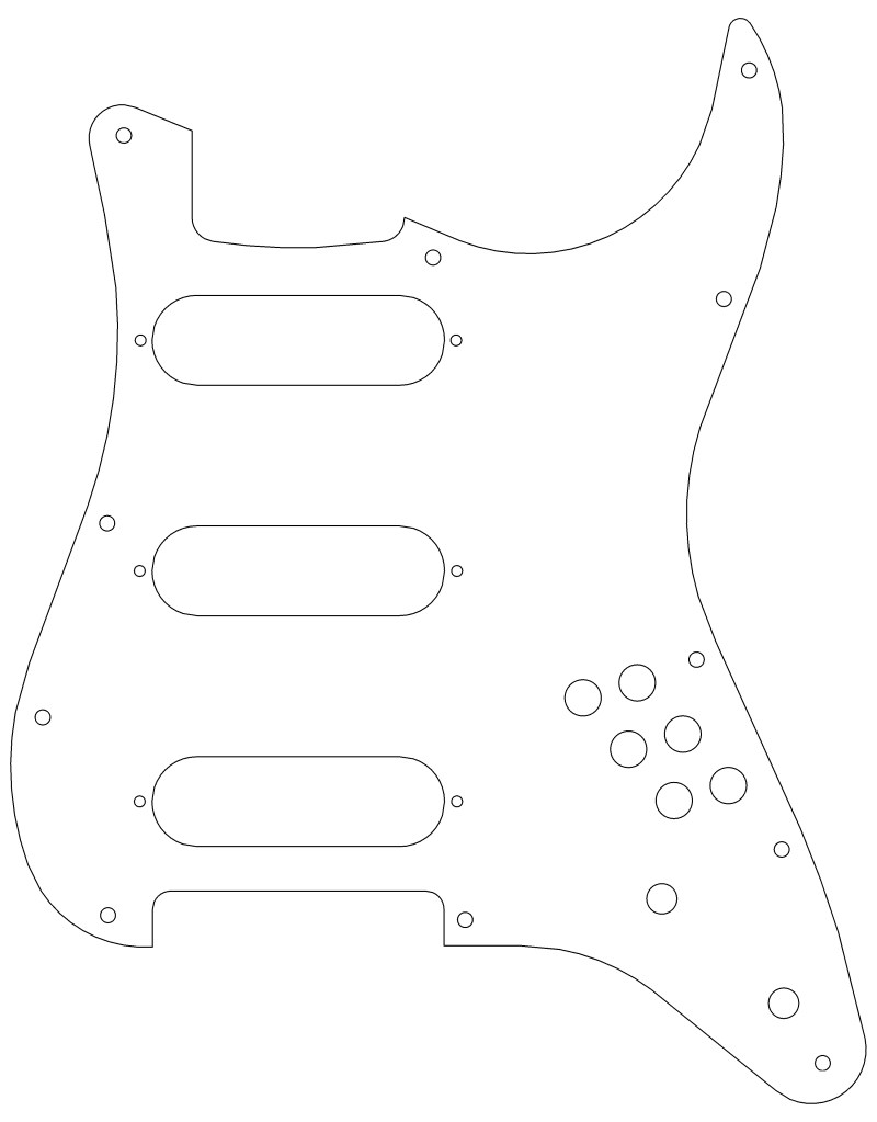
Note that I changed the shape of the cutout around the tremolo plate to reduce the gap between the front edge of the plate and the pickguard. This is my aesthetic preference because I don’t like the large gap on the OEM design and is not a design error. Please bear this in mind if you download my design sketches and use them for your own project.
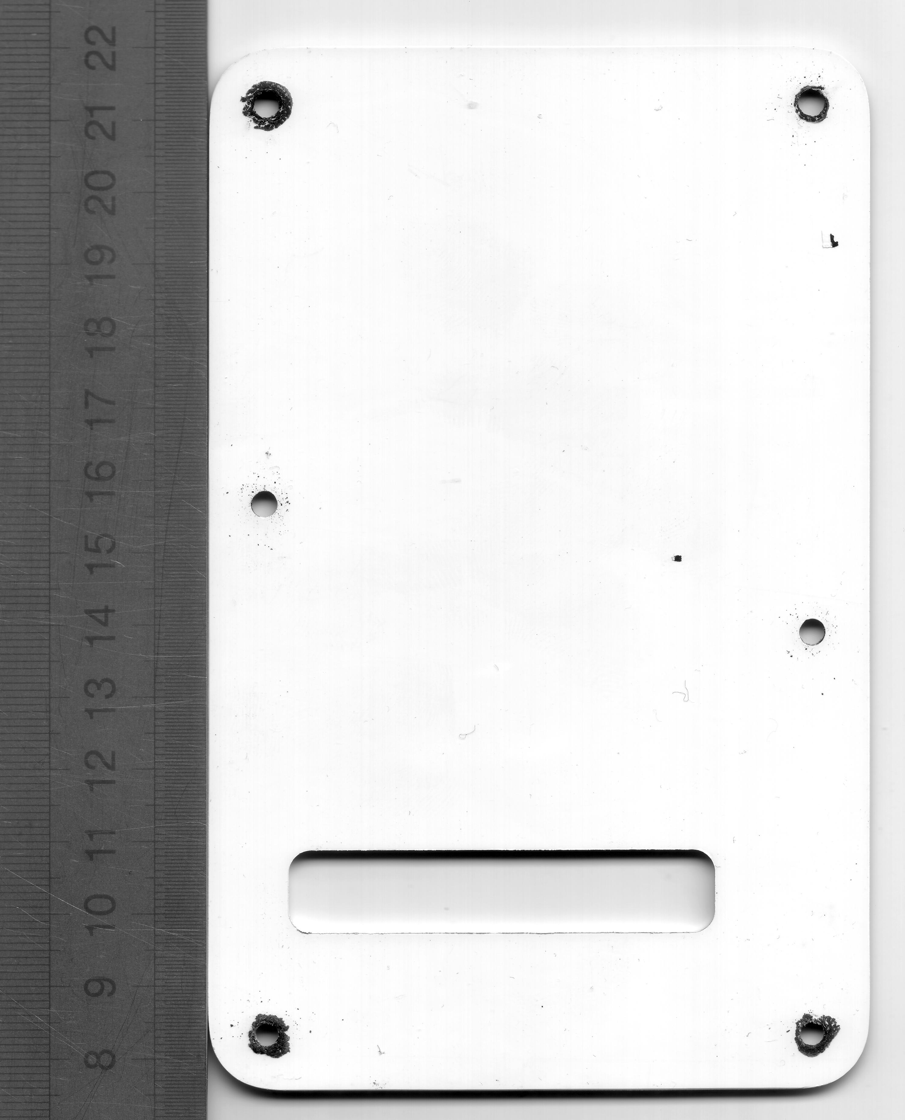

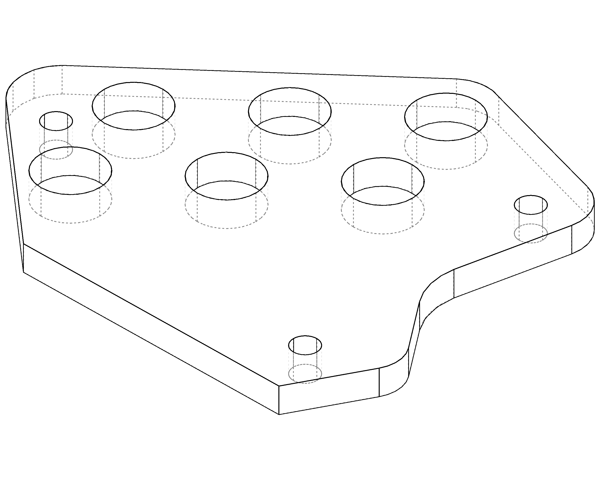
I also transferred the back plate design into CAD because I wanted to CNC cut a new one from pearloid material and worked up a design for a perspex mounting plate for the KAT PCB. I discussed the design, CNC cutting and thermosetting brass threaded inserts into a similar perspex mounting solution for the six Switchcraft DPDT parallel slide switches in my Burns Red Special conversion.
Next article:
Part 2: Pickups
Return to the project home page:
https://dsgb.net/projects/maycaster/
