Body and Pickguard Design
The first scope change on this project was from modifying the commercial BMG Mini May body to designing a new body with a more authentic outline shape to accommodate the original BMG Mini May neck. I decided to stick with a solid, one piece body and use mahogany to avoid the requirement to do any veneer work. This was both for simplicity’s sake and also to ensure that the guitar, which would likely be used by a child, would be robust enough to stand up to the odd bash or drop. First, I traced the outline of the original Red Special body (including control cavity and tremolo mechanism cavity) and reduced them to 75% of full size. I then scanned the BMG Mini May neck heel and modified the body profile to accommodate it.
After defining the outline, the next most important process was to identify the constraints. The primary constraint is obviously scale length (which sets the bridge centreline) and, from that, the pickup spacing can be determined; the BMG Mini May scale length is nominally 19 inches (482.6 mm). The original guitar had issues relating to the bridge position being too far forward to accommodate the substantial intonation corrections required (low E: +1 mm, B: +2 mm, G: +4 mm, D: +2 mm, A: +4 mm and high E: +6 mm giving an average offset of +3.16 mm. I judged that offsetting the bridge centreline by +5 mm was probably sensible.
The third constraint was the gap between the end of the neck pocket and the front of the neck pickup cavity. 5 mm seemed like a sensible firewall and this yielded pickup centreline distances of 41.5 mm. The fourth constraint was the size of the tremolo mechanism cavity which had to accommodate César’s hardware which I described in Part 2. The fulcrum plate could be used without any modification but I made the tailpiece as narrow as possible by removing almost all the material on the bass side and as much of the material on the treble side as possible without compromising the structural integrity of the M5 thread for the tremolo arm.
Further constraints were introduced by the physical limitations of the scaled control cavity and the size and throw of the Switchcraft DPDT parallel slide switches. The range of Switchcraft DPDT parallel slide switches was evaluated to see if smaller versions were available that would allow a more authentic longitudinal spacing. The 56206L version has overall casing width of 15.88 mm (mounting ears cut off), a switch throw of 8.74 mm and switch width of 3.18 mm. However, it was considered that even these miniature switches were not small enough to allow an authentic spacing so it was decided to stick with the standard 46206LRX variant has an overall casing width of 22.35 mm (mounting ears cut off), a switch throw of 11.94 mm and switch width of 5.84 mm.
Once these constraints were fixed, I created the pickguard outline in much the same way as the body outline, by tracing the original, scaling it down to 75% then patching in the neck heel outline. The pickup apertures and roller bridge aperture were added then I began the iterative process of scrutinising and modifying the overall outline to yield the best compromise between an authentic look and a good fit around the apertures, control cavity and tremolo cavity. The resulting overall design is illustrated below in plan view with the body axial centreline and the normal bridge centreline position drawn in. Note the very tight tolerance between the tremolo cavity and the half moon plate and between the bridge pickup left mounting tab aperture and the edge of the scratch plate.
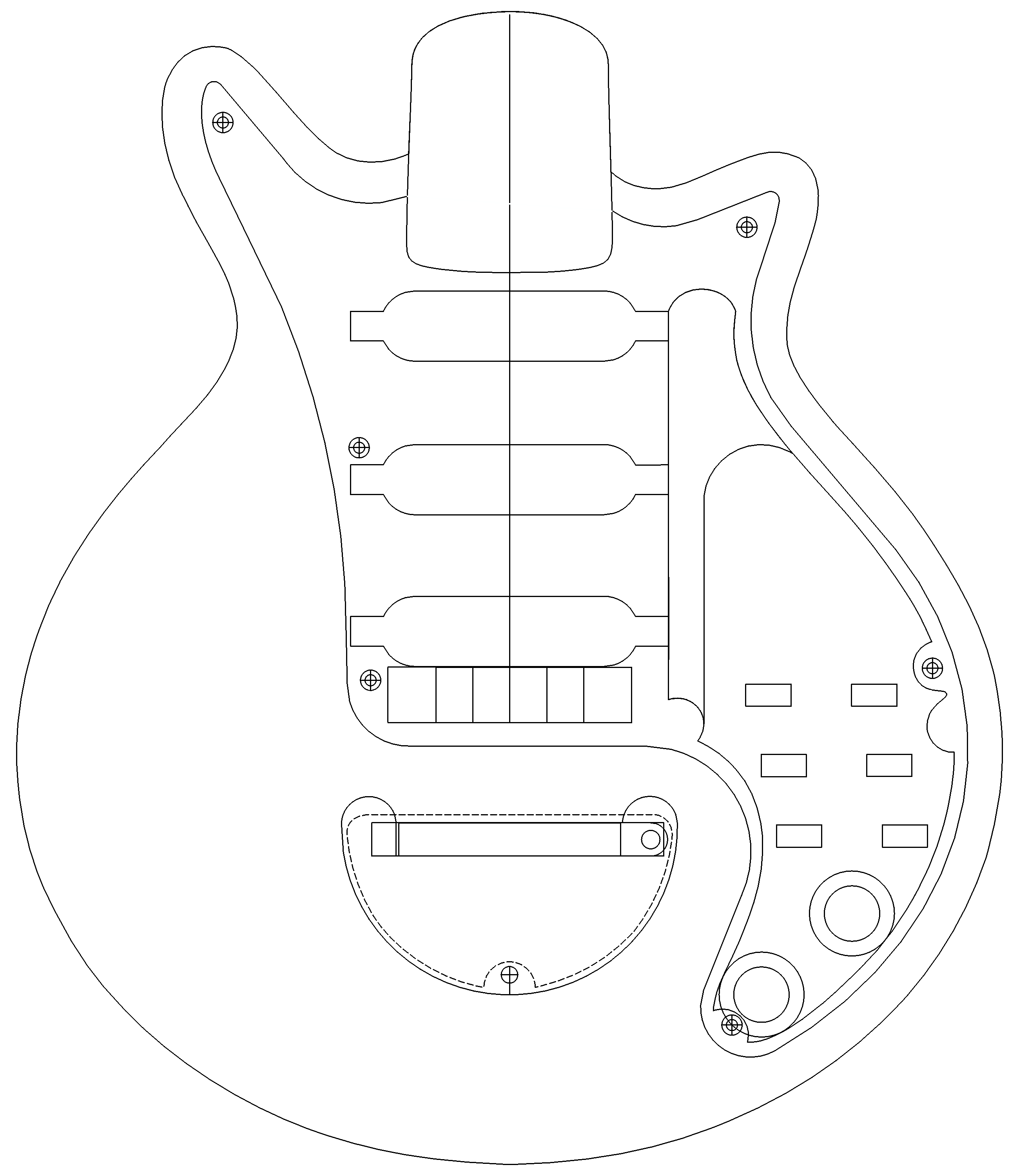
Initially, I did not design in the shelf feature on which the polarity posts are mounted on the original Brian May Red Special but added it as an afterthought to at least give me the option of incorporating polarity posts. I reasoned that even if there wasn’t enough room to do this without the internal components becoming too fiddly or lacking robustness, it would at least serve as a more authentic internal feature for anybody opening up the guitar in future. As it transpired, it ultimately served a purpose as a common grounding connections for the pickup body earth wires and the control plate.
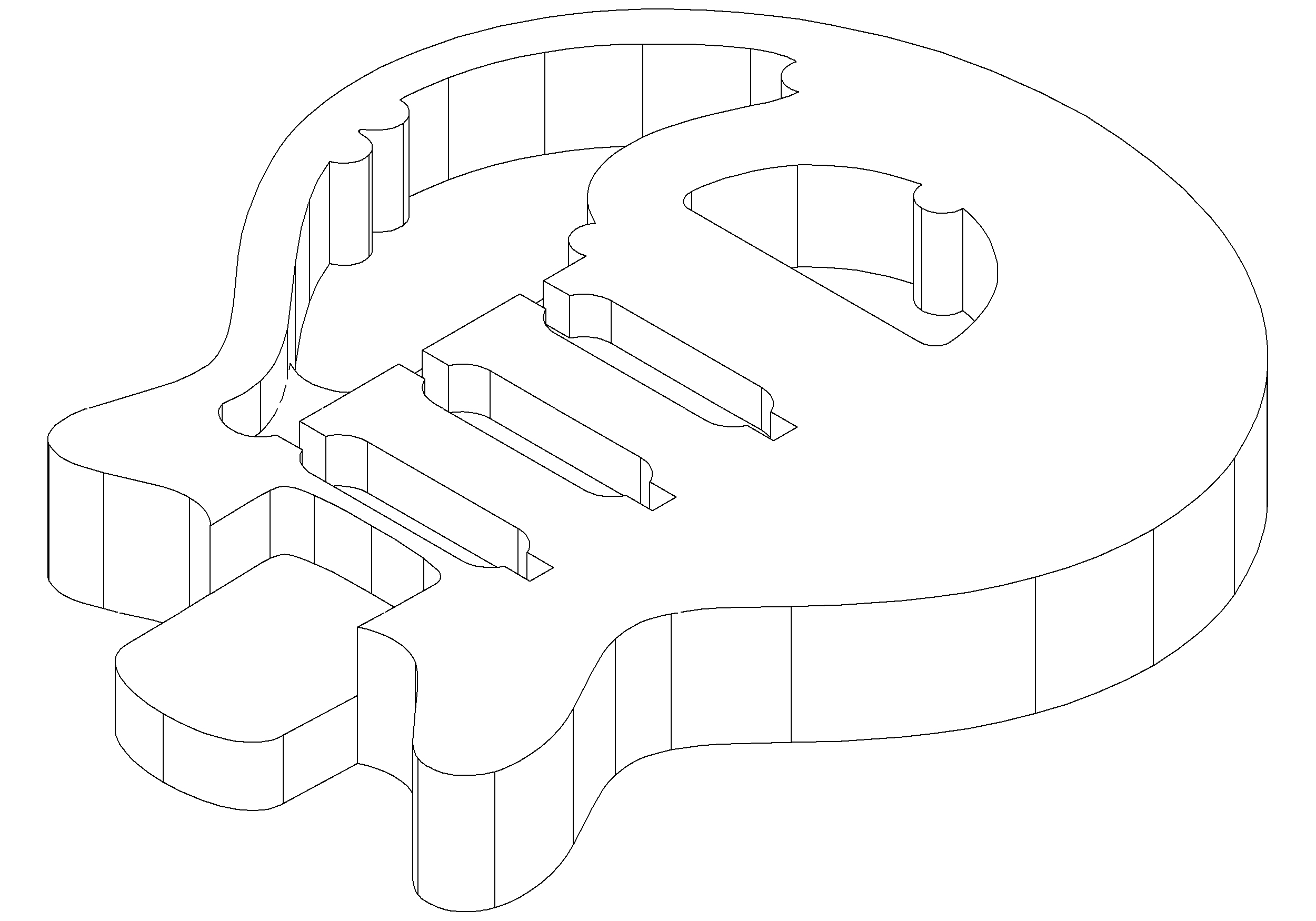
Once the overall outlines are all fixed in 2D space, the 3D object can easily be created by just changing the depth parameter (z axis) of each 2D shape to the required size, e.g. 40 mm for the main body. Cavities can be created by using a Boolean subtract feature which involves selecting the minuend (main object) and subtrahend (object to be subtracted from the main) and activating the feature. In this way, complex objects can be built up from simple shapes. I considered building in a rebate around the top and bottom edges for the edge binding, but eventually rejected this for several reasons: to minimise both the design and cut complexity on grounds of cost, time (and quality because I believed that I could control the process better with a handheld trimmer/router in case I incorrectly estimated the dimensions of the purfling). There is always the risk of damaging a pre-formed edge profile so I didn’t rout the rebate until I had completed the hand carving work. I believe that it is a better strategy to finalise design details when you have the hardware and materials physically available to you, rather than make assumptions and risk having to bodge a precise machine cut further down the line.


Aluminum Control Plate Design
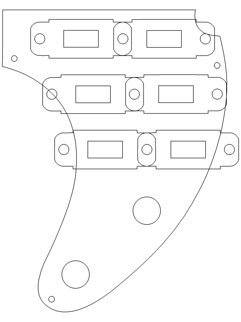
It quickly became obvious that due to the highly constrained space in the control cavity, the only credible option for mounting the electronic components was the single piece control plate as deployed on the KZ Super Brian May Red Special replica. I fashioned this manually from 2 mm thick aluminium plate by printing out the design directly from TurboCAD at 1:1 scale on paper, attaching it to the metal plate with clear adhesive tape, scoring around it with a heavy duty knife then cutting it using a diamond-plated cutting disc on a rotary multi-tool. The switch apertures were initially drilled with a standard 6 mm HSS drill and the excess filed out using a small diamond-coated hand file. The potentiometer mounting holes were drilled out using a standard 9.5 mm HSS drill. Finally, I dressed to the desired profile again using a diamond-coated file.
I designed the control plate to be mounted onto the three semi-circular posts using M2 machine screws screwed into M2 brass threaded inserts. M2.5 machine screws would be used to mount the switches to it and holes of the appropriate diameter were drilled using the Clarke CMD-10 micro milling/drilling machine. This was the first significant investment in tools and equipment for this (and future) hobby projects and it replaced a much cheaper belt-driven CDP101B model drill press which, disappointingly, did not have the required precision for this work due to eccentricity in the nylon sheaves.
Neck Design
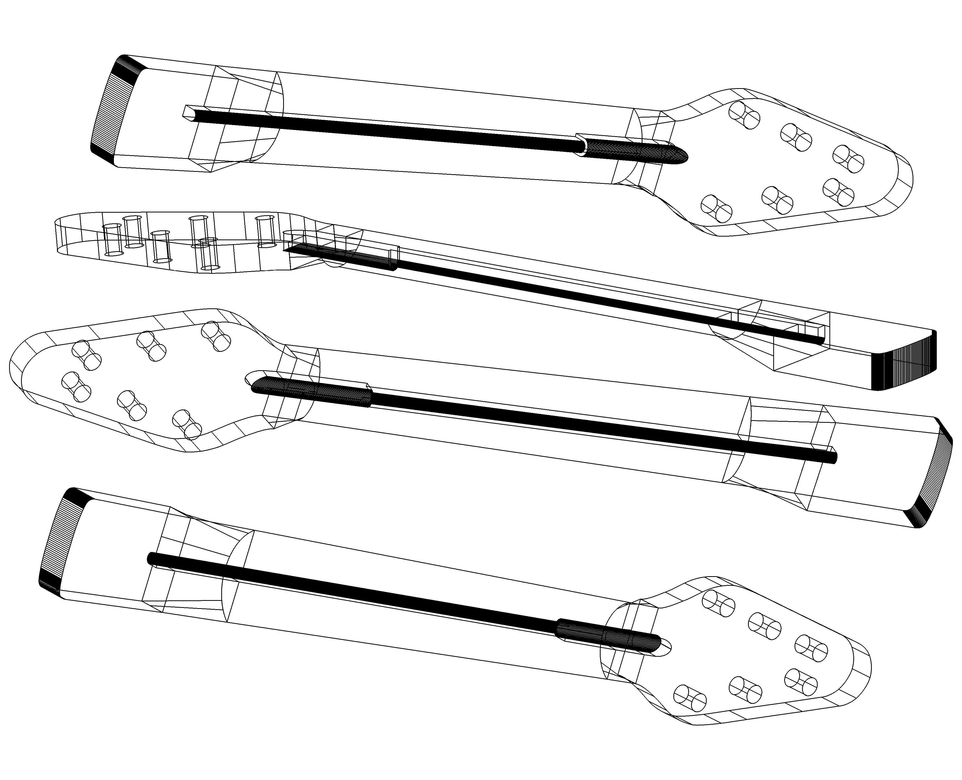
The second scope change of the project was from reusing the original BMG Mini May neck (which was a two piece item of natural finished light coloured wood with a painted and lacquered upper headstock surface) to remaking the neck using CNC routing from a block of Honduras mahogany tonewood. After I had evaluated the capabilities of TurboCAD (I had version 19.2 Professional Platinum at the time but have since updated to 2016 Professional), I decided that the neck would be best designed using a modular approach consisting of five individual sections: headstock (same size as the original), a semi-cylindrical section and a heel (both with the same profiles as the original BMG Mini May) and two transition sections (fillets in effect): one between the headstock and semi-cylinder and one between the semi-cylinder section and the heel. Apart from the unsatisfactory finish on the BMG Mini May’s neck, the main motivation for designing a new neck was to evaluate the capabilities and limitations of TurboCAD and commercial CNC routing for producing complex shapes and gain some experience using the 3D CAD package before deciding whether to use this process for making a full size long tenon neck, or whether to rout it manually using templates.

TurboCAD has several features for creating 3D objects from two or more 2D shapes and for joining two or more 3D objects, one of which is called lofting. However, when I attempted to join the headstock, middle semi-cylinder and heel sections directly using this lofting feature, it didn’t work because TurboCAD doesn’t allow lofting between two 3D objects if the faces to be connected are not simple geometric shapes. For example, this wouldn’t work on the heel section, presumably because the shape was created by extruding (adding depth) to a polyline (a compound outline made by joining linear and curved sections). This must result in a face which is not mathematically distinct for some reason. Perhaps more sophisticated commercial software such as Autodesk’s AutoCAD or SolidWorks have more powerful or intelligent features but these are inaccessible to the amateur on grounds of cost. Hence it was necessary to create a workaround in the form of adding intermediate objects (the transition fillets) between the three parts.


Next article:
Part 4: Body CNC Cut
Previous article:
Part 2: Hardware
