It was necessary to make some minor alterations to the Brian May Red Special guitar body to facilitate final assembly. I have illustrated this article with plenty of photographs of the work because the colour and grain show up really well. This work involved the following tasks:
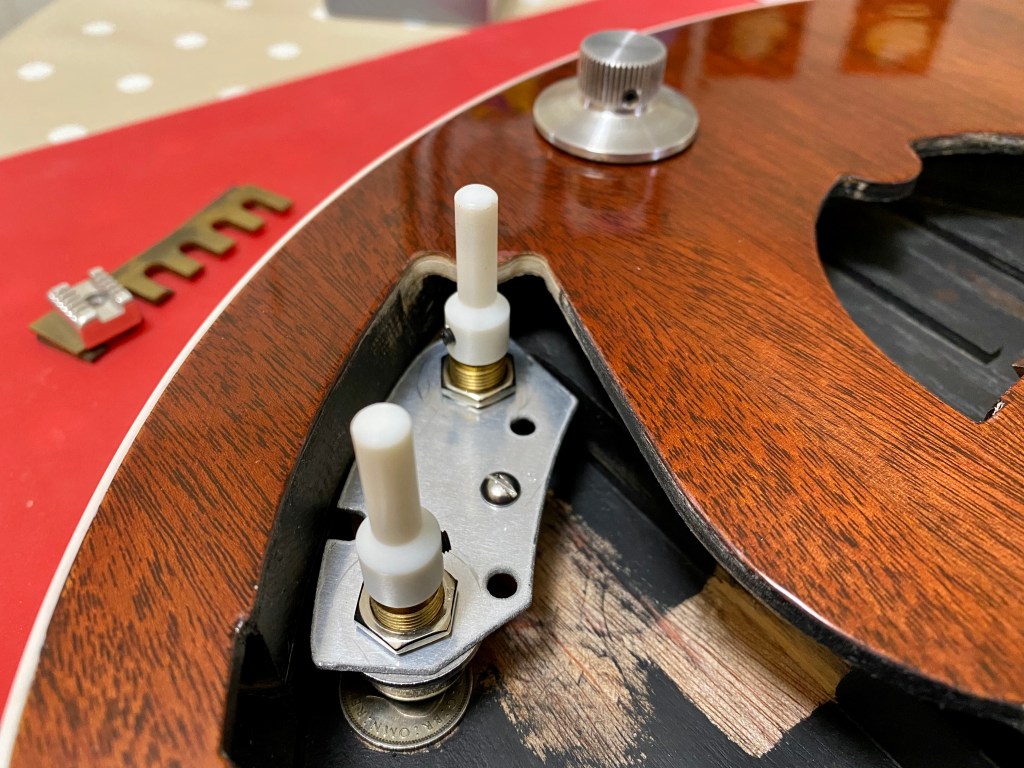
(a) Routing away the original cuboid mounting block which was designed in and fashioned during the original CNC cut but was not in the correct position. In retrospect, I shouldn’t have bothered trying to estimate its position and should have left it out, saving some milling time and followed this procedure: using a spare aluminium plate, I made several new cuboid blocks (1/2″ x 1/2″ x 5/8″ high) from oak using my CNC machine. I pilot drilled one to accept a mounting screw and attached it to the plate along with two spare Bourns potentiometers and the pair of nylon potentiometer shaft extenders. With a second cuboid block positioned underneath to stabilise it, I placed the pickguard over the loose assembly and positioned it in the desired position. I then lifted off the pickguard carefully and marked the position on the base of the control cavity. I then glued the oak cuboid in position with superglue.

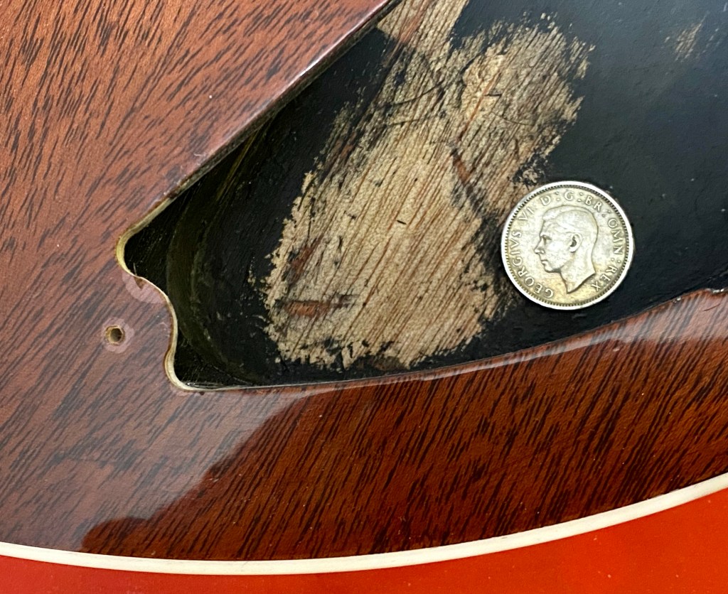
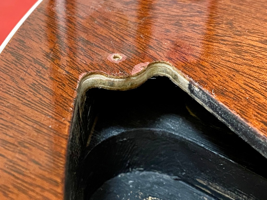
(b) Another modification required to allow the potentiometer and capacitor mounting plate to be positioned correctly was a reprofile of the overhang region adjacent to the volume potentiometer shaft where the pickguard mounting screw is located. I drew up my plans using the x-rays and overhead photographs of the original guitar in the public domain. These all have parallax error to a greater or lesser degree, so evaluating the shapes of the control cavity involved a good deal of judgement and cross-checking. I eventually reached the point of diminishing returns with this iterative process during the design phase and resolved to make it fit during final assembly. I carefully drilled out the region to a more suitable profile using a 1/4″ router bit, finished it off manually with my preferred type of abrasive paper: 120 grit 3M Stikit Gold.

(c) I test fitted the roller bridge for the first time after gluing in the 12 mm high brass inserts and abrading dried superglue off the lacquer surface. These inserts have a heavy diamond pattern knurl turned into the outside surface and are internally tapped with an M3 thread, the nearest metric equivalent to the original which used 6BA Hank rivet nuts. Various designs of brass insert for wood and plastic are freely available now but in 1963, it was another intelligent solution by Brian and Harold. I originally planned to install Hank rivet nuts but I deemed these custom inserts which came with the hardware set a better option. The alignment was highly satisfactory but required the holes in the pickguard to be opened out to 1/8″ to allow some clearance.
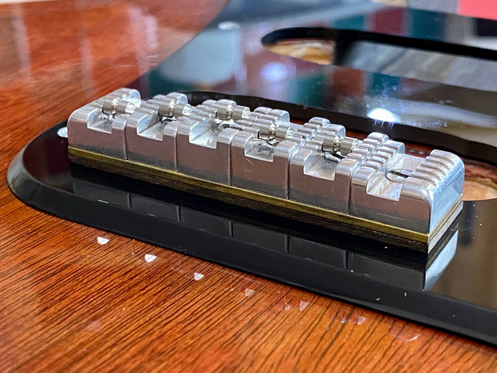

If you want to know more about the frictionless roller bridge fitted to Brian May Red Special replicas, please check out this YouTube video that I released in September 2025. I discuss design, function and installation and show you the fasteners and shims used to install it and set the desired string action. To illustrate the discussion, I show you two professionally engineered assemblies with different interpretations of Brian’s original design and compare these with the one I made in January 2022 for a brief time lapse video on the CNC milling with no commentary.
(d) Lastly, I further modified the rebates for the Burns Tri-Sonic pickups by opening out the mounting tab area and the curved edge sections. I positioned the pickups centrally, checked the correct positioning by placing the pickguard and pickup surrounds over them and marked the position of the mounting screw holes. Only the middle pickup will require its base mounting tabs to be slightly modified by enlarging the screw holes towards the pickup to ensure that they are not too near the edges of the wood.


Next article:
Part 57: Control Cavity Copper Foil Shielding
Previous article:
Part 55: Body Assembly
